Liquid crystal display device

a liquid crystal display and display device technology, applied in liquid crystal compositions, instruments, chemistry apparatus and processes, etc., can solve the problems of low brightness, low transmission intensity, and low brightness, and achieve high brightness, reduce quenching patterns, and high transmission intensity

Inactive Publication Date: 2005-09-27
SHARP KK
View PDF6 Cites 5 Cited by
  • Summary
  • Abstract
  • Description
  • Claims
  • Application Information

AI Technical Summary

Benefits of technology

[0010]An object of the present invention is to provide a liquid crystal display device of a vertical alignment mode having a high transmission intensity, i.e., high brightness, the invention realizing the liquid crystal display device (A) by reducing a quenching pattern, which is generated according to a relationship between (i) directions of polarization axes of two polarization plates which are arranged in a cross nicole manner and (ii) an alignment direction of liquid crystal molecules under applied voltage, to such a degree as to be completely unrecognizable for a user, and (B) by determining optical physical property values that can maximize the transmission intensity.
[0012]With this arrangement, when no voltage is applied across the first and the second electrodes, the liquid crystal molecules in the liquid crystal layer are vertically aligned. This causes no birefringent effect or optical rotatory effect, so that the light passes through the liquid crystal layer and leaves the liquid crystal layer almost unaffected. On the other hand, when a voltage is applied, the liquid crystal layer assumes a twisted structure and the liquid crystal molecules are aligned parallel to the substrates, thereby causing the birefringent effect and optical rotatory effect. As a result, the state of light that leaves the liquid crystal layer can be changed depending on whether or not a voltage is applied, enabling the display state to be changed in accordance with the voltage.
[0013]The inventors of the present invention have diligently worked on a liquid crystal display device of a vertical alignment mode (A) to reduce a quenching pattern, which is generated according to a relationship between (i) directions of polarization axes of polarization plates which are arranged in a cross nicole manner and (ii) an alignment direction of liquid crystal molecules when a voltage is applied, to such a degree as to be unrecognizable for a user, and (B) to determine optical physical property values that can maximize the transmission intensity. As a result, the inventors of the present invention have accomplished the present invention by finding that (1) the liquid crystal molecules in the vicinity of the substrates remain vertically aligned even under applied voltage by the pre-applied regulating forces acting on the liquid crystal molecules, because the liquid crystal molecules are vertically aligned under no applied voltage in the liquid crystal display device of a vertical alignment mode, (2) the thickness of a portion of the liquid crystal molecules where the birefringent effect and optical rotatory effect are generated is accordingly thinner than the actual thickness of the liquid crystal layer, and (3) the thickness of this portion of the liquid crystal molecules varies in accordance with an applied voltage.
[0014]Namely, in the liquid crystal display device of the present invention, the liquid crystal layer has defined values for d / p and d·Δn / λ that respectively fall in the foregoing ranges, i.e., the values according to the maximum applied effective voltage on the first and second electrodes, and that have been set by taking into account the inclined alignment of the liquid crystal molecules in the vicinity of the substrates under applied voltage. As a result, it is possible to suppress the quenching pattern to a such degree as to be unrecognizable for a user, thereby realizing a liquid crystal display device capable of realizing brighter display with higher display quality, compared with a device in which the quenching pattern is recognized. Here, the quenching pattern that can be reduced in the present invention is a quenching pattern that generates on the electrodes within picture elements.

Problems solved by technology

However, the TN mode liquid crystal display device has problems that contrast decreases and tone characteristic inversion is likely to occur when viewed on an angle.
Under these conditions, a serious quenching pattern remains over a large area and with high intensity, resulting in decrease in transmission intensity and decrease in brightness.
However, this publication does not have a notion of eliminating the quenching pattern, or improving the transmittance by eliminating the quenching pattern.
Further, the publication does not disclose optimizing the quenching pattern or transmittance.

Method used


Image

  • Liquid crystal display device
  • Liquid crystal display device
  • Liquid crystal display device

Examples


Embodiment Construction

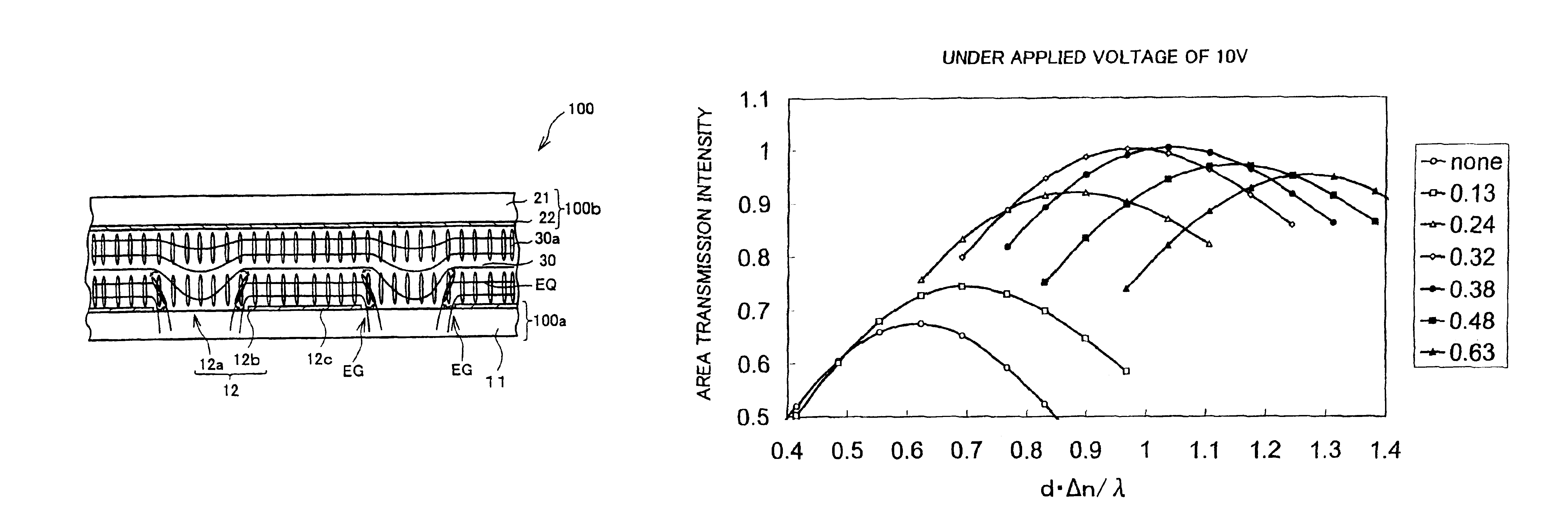
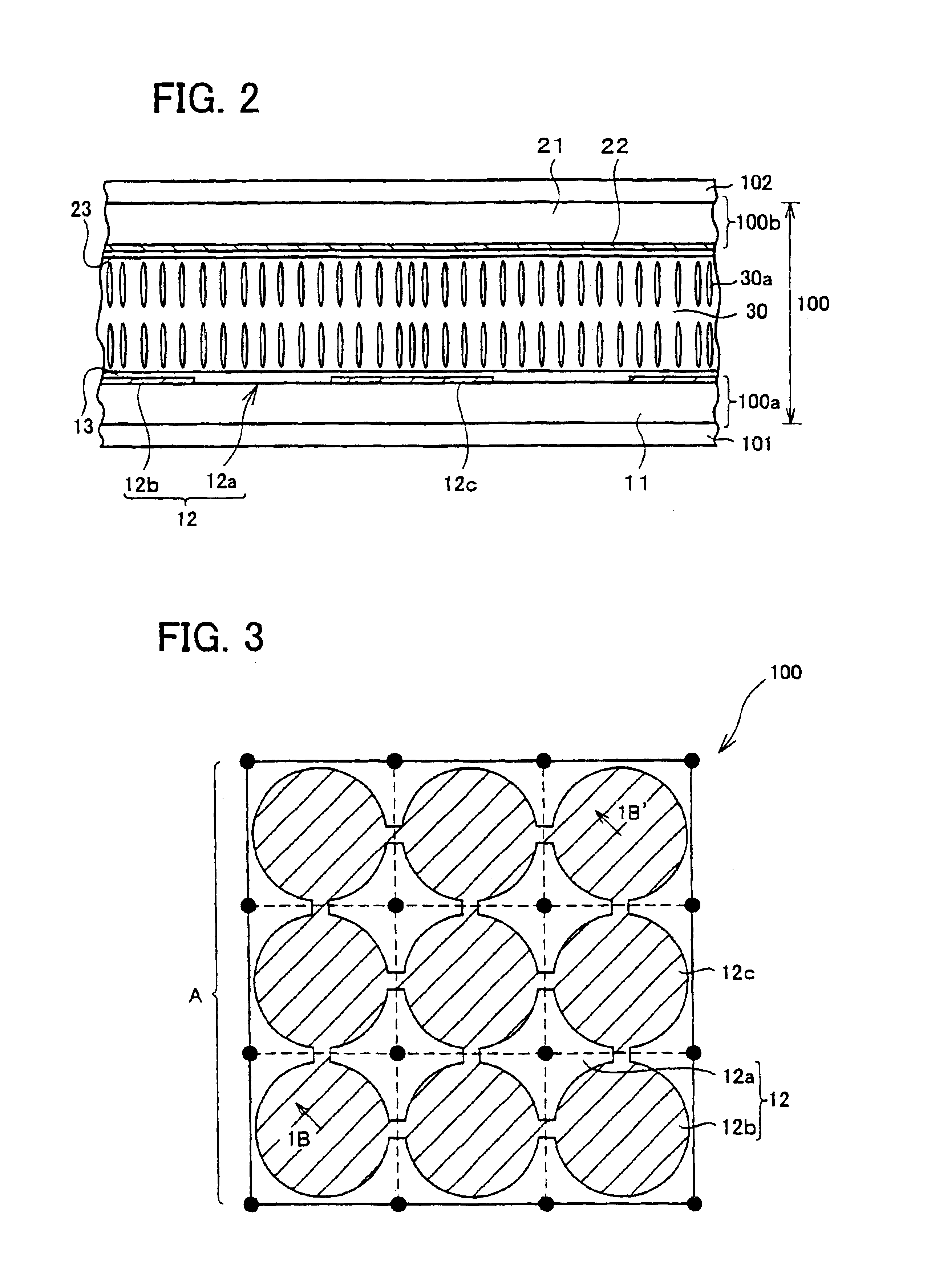
[0066]The following will explain an embodiment of the present invention with reference to FIGS. 1 through 50. A liquid crystal display device in accordance with the present embodiment does not generate a quenching pattern in spite of its high area-transmission-intensity, and thereby produces high quality display. As shown in FIG. 2, the liquid crystal display device is provided with a liquid crystal cell 100 of a vertical alignment mode, and polarization plates 101 and 102 that are respectively disposed on both sides of the liquid crystal cell 100.

[0067]The liquid crystal cell 100 includes an active matrix substrate 100a such as a thin film transistor (TFT) substrate (hereinafter referred to as “thin film transistor (TFT) substrate”), a counter substrate 100b such as a color filter substrate (hereinafter also referred to as “color filter substrate”), and a liquid crystal layer 30 interposed between the TFT substrate 100a and the counter substrate 100b. Note that, the TFT substrate 1...


PUM

PropertyMeasurementUnit
thicknessaaaaaaaaaa
voltageaaaaaaaaaa
angleaaaaaaaaaa

Abstract

A liquid crystal display device of a vertical alignment mode is provided in which a quenching pattern, which is generated by such liquid crystal molecules whose in-plane component of the alignment directions under applied voltage is aligned along the cross nicole directions, is unrecognizable for a user. In the liquid crystal display device of a vertical alignment mode, a liquid crystal layer is has a defined value of d / p between 0.0021×(Vmax)2−0.0458×(Vmax)+0.65 and 0.0021×(Vmax)2−0.0458×(Vmax)+0.50, and a defined value of d·Δn / λ between −0.00026×(Vmax)3+0.016×(Vmax)2−0.2281×(Vmax)+2.124 and −0.00026×(Vmax)3+0.016×(Vmax)2−0.2281×(Vmax)+1.7603, where Vmax [V] is the maximum applied effective voltage applied to the liquid crystal layer.

Description

[0001]This application is a continuation of U.S. Ser. No. 10 / 654,403 filed Sep. 4, 2003 now U.S. Pat. No. 6,822,724, which claims priority of JP application 2002-262152 filed Sep. 6, 2002, both of which are incorporated herein by reference.FIELD OF THE INVENTION[0002]The present invention relates to a liquid crystal display employing a vertically alignment mode.BACKGROUND OF THE INVENTION[0003]Conventionally, liquid crystal devices have been widely used as a screen for word processors and computers, and recently have been pervasive as a screen for televisions. Most of the liquid crystal display devices employ a TN (Twisted Nematic) mode. However, the TN mode liquid crystal display device has problems that contrast decreases and tone characteristic inversion is likely to occur when viewed on an angle.[0004]To improve a viewing angle characteristic in an angled direction, a liquid crystal display device employing a VA (Vertically Alignment) mode has come to receive attention in these ...

Claims


Application Information

Patent Timeline
Patent Type & Authority Patents(United States)
IPC IPC(8): G02F1/13G02F1/139G02F1/1343G02F1/1333G02F1/1337
CPCG02F1/1393G02F1/134336G02F1/133707G02F1/1337
Inventor OGISHIMA, KIYOSHIKUBO, MASUMI
Owner SHARP KK
Why Eureka
Try Eureka