Thin-film magnetic head with thin-film coil of low resistance

a thin-film coil and magnetic head technology, applied in the field of thin-film magnetic head, can solve the problems of increasing the resistance of increasing the resistance of the linear conductor portion and the resistance of the entire thin-film coil, and increasing the probability of the magnetic pole portion colliding with the recording medium, etc., to achieve excellent recording characteristics, small resistance, and small magnetic path length

Inactive Publication Date: 2005-09-27
HEADWAY TECH INC +1
View PDF8 Cites 26 Cited by
  • Summary
  • Abstract
  • Description
  • Claims
  • Application Information

AI Technical Summary

Benefits of technology

[0026]It is an object of the invention to provide a thin-film magnetic head which is small in magnetic path length and thus excellent in reco

Problems solved by technology

Under the circumstances, the conventional thin-film magnetic heads have had the problem that the thin-film coil increases in resistance when the yoke length is reduced to improve the recording characteristics at high frequency bands.
Nevertheless, if the yoke length is reduced as described above and the number of turns of the thin-film coil is increased at the same time, the conventional thin-film magnetic heads become yet smaller in the width of the linear conductor portions, which results in further increases in the resistance of the linear conductor portions and the resistance of the entire thin-film coil.
As the resistance of the thin-film coil increases, there arises a problem that the magnetic pole portions can protrude toward the recording medium due to heat occurring from the thin-film coil and thus the magnetic pole portions become more likely to collide with the recording medium.
Thus, in the conventional thin-film magnetic heads it has been unfeasible to reduce the yoke length considerably from the viewpoint of

Method used


Image

  • Thin-film magnetic head with thin-film coil of low resistance
  • Thin-film magnetic head with thin-film coil of low resistance
  • Thin-film magnetic head with thin-film coil of low resistance

Examples


first embodiment

[First Embodiment]

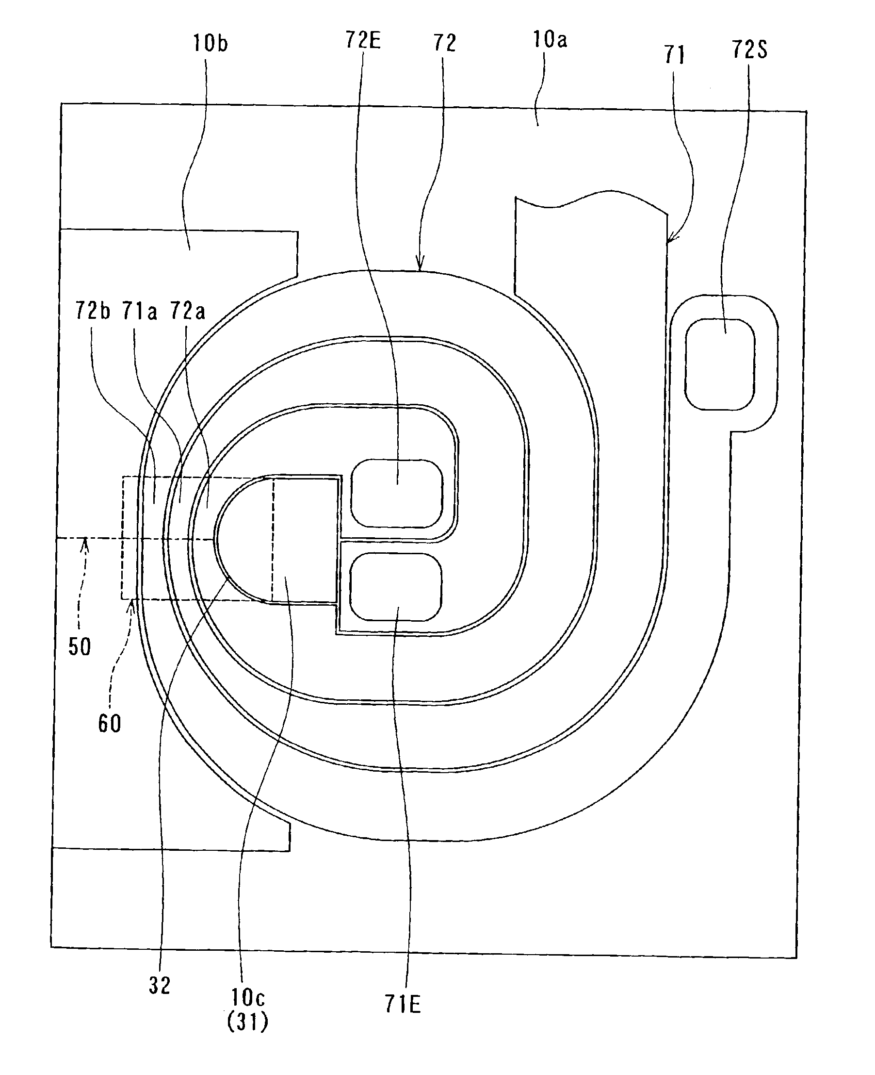
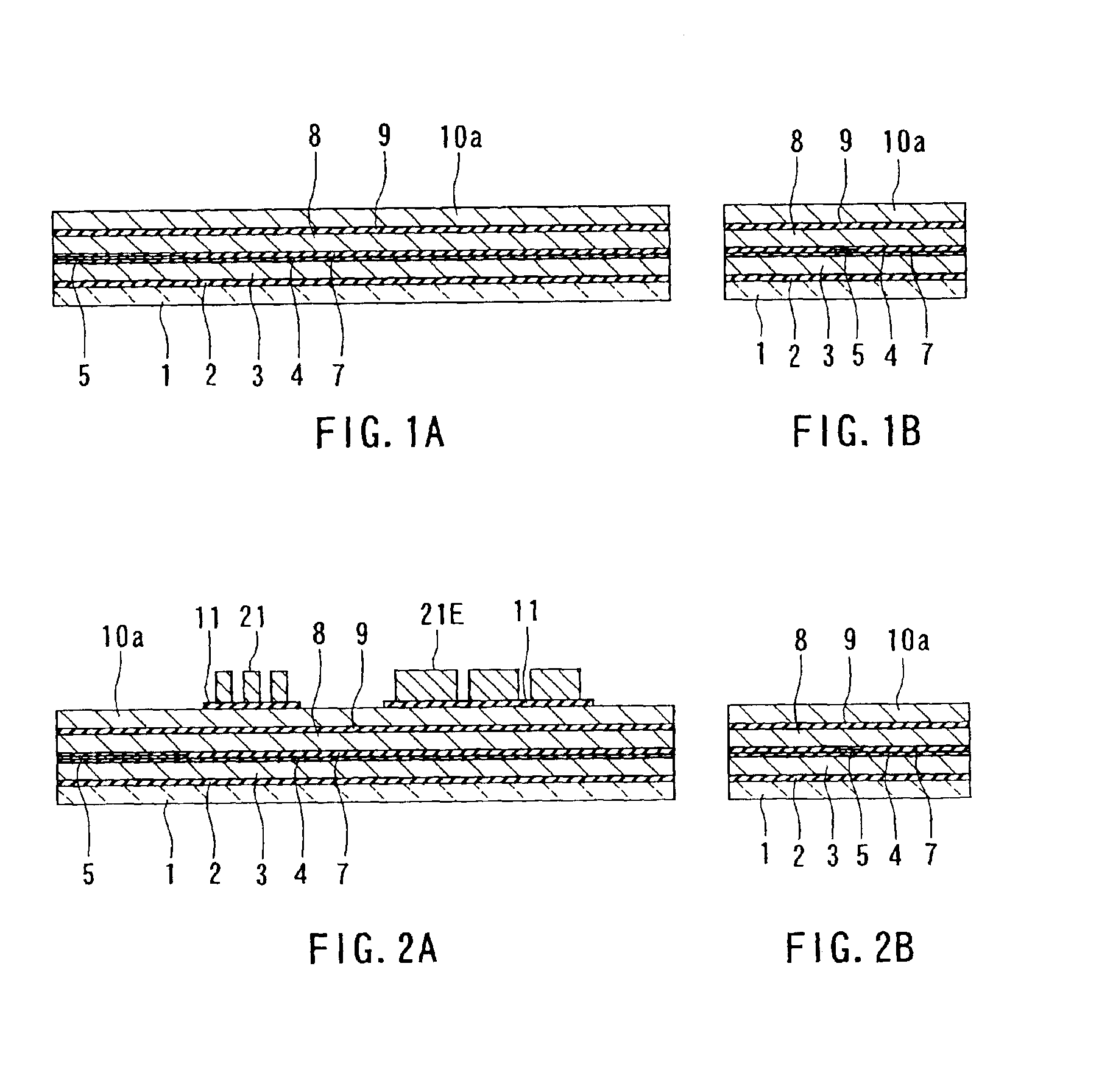
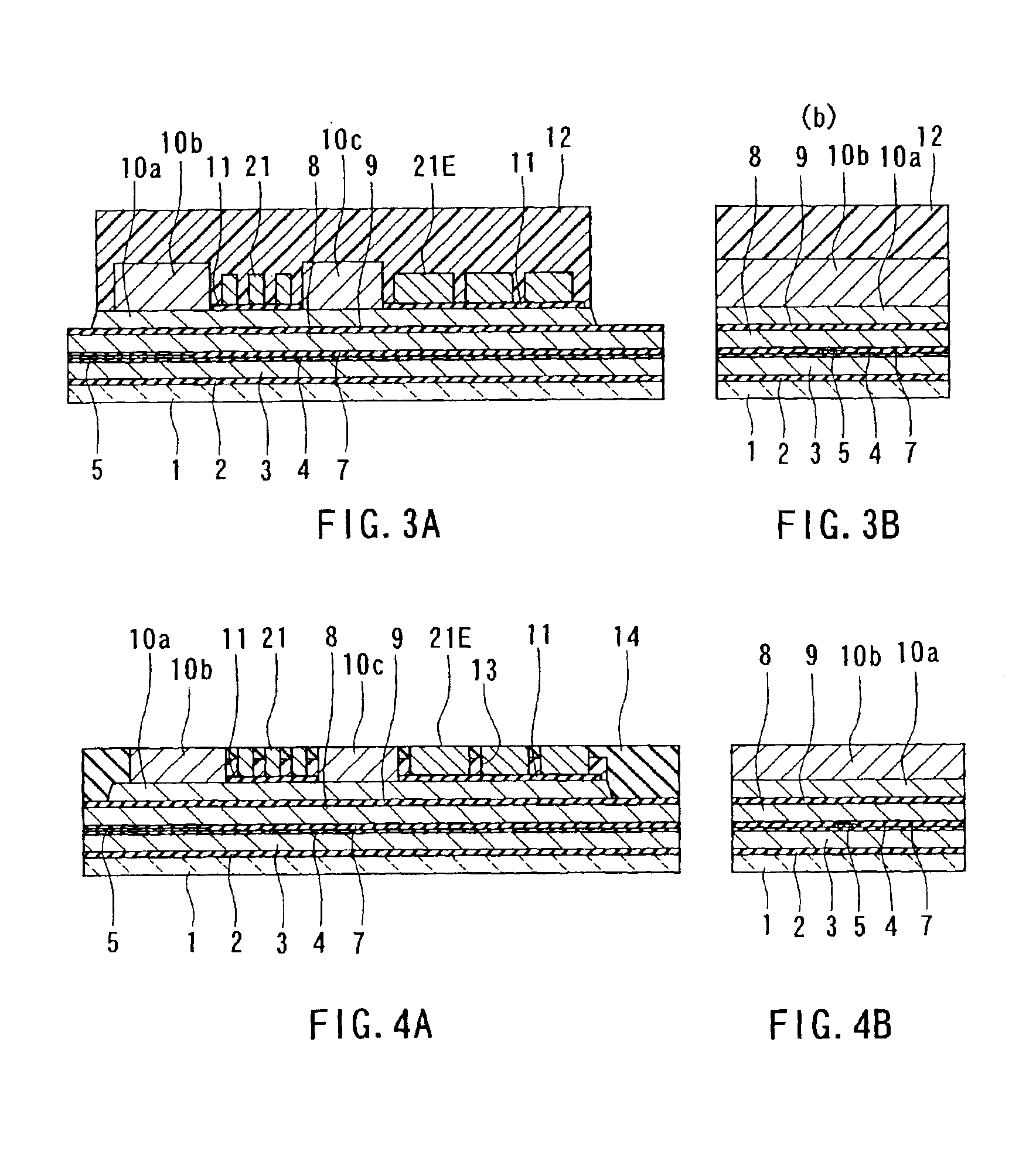
[0127]First, a method of manufacturing a thin-film magnetic head according to a first embodiment of the invention will be described with reference to FIGS. 1A to 13A, FIGS. 1B to 13B, FIG. 14, and FIG. 15. FIGS. 1A to 13A are cross sections each orthogonal to the air bearing surface and the top surface of the substrate. FIGS. 1B to 13B are cross sections of the magnetic pole portion each parallel to the air bearing surface. FIG. 14 and FIG. 15 are plan views for illustrating the method of forming a thin-film coil of the present embodiment.

[0128]In the method of manufacturing the thin-film magnetic head of the present embodiment, as shown in FIGS. 1A and 1B, an insulating layer 2 made of alumina (Al2O3), for example, is first deposited to a thickness of approximately 2 to 5 μm on a substrate 1 made of aluminum oxide and titanium carbide (Al2O3—TiC), for example. Next, a bottom shield layer 3 intended for a reproducing head, made of a magnetic material such as Permal...

second embodiment

[Second Embodiment]

[0219]Now, a thin-film magnetic head and a method of manufacturing the same according to a second embodiment of the invention will be described with reference to FIGS. 30A to 45A, FIGS. 30B to 45B, and FIGS. 46 to 50. FIGS. 30A to 45A are cross sections each orthogonal to the air bearing surface and the top surface of the substrate. FIGS. 30B to 45B are cross sections of the magnetic pole portion each parallel to the air bearing surface. FIGS. 46 to 50 are plan views for illustrating the method of forming a thin-film coil of the present embodiment.

[0220]The manufacturing method of the present embodiment is the same as that of the first embodiment up to the step of forming the first layer 10a of the bottom pole layer 10. The bottom pole layer 10 includes the first layer 10a, and second to seventh layers 10b-10g to be described later.

[0221]Then, in the present embodiment, as shown in FIGS. 30A and 30B, an insulating film 11 made of alumina, for example, is formed on...

third embodiment

[Third Embodiment]

[0274]Now, a thin-film magnetic head and a method of manufacturing the same according to a third embodiment of the invention will be described with reference to FIGS. 51A to 62A and FIGS. 51B to 62B. FIGS. 51A to 62A are cross sections each orthogonal to the air bearing surface and the top surface of the substrate. FIGS. 51B to 62B are cross sections of the magnetic pole portion each parallel to the air bearing surface.

[0275]The manufacturing method of the present embodiment is the same as that of the second embodiment up to the step of patterning the first layer 10a by selectively etching the first layer 10a using the photoresist layer 12 as a mask, as shown in FIGS. 31A and 31B.

[0276]Then, in the present embodiment, as shown in FIGS. 51A and 51B, after removing the photoresist layer 12, an intercoil insulating film 83 is formed to cover the entire top surface of the laminate. The material, thickness and forming method of the intercoil insulating film 83 of this e...


PUM

PropertyMeasurementUnit
Electrical resistanceaaaaaaaaaa
Shapeaaaaaaaaaa
Radiusaaaaaaaaaa

Abstract

A thin-film magnetic head comprises a medium facing surface, a bottom pole layer, a top pole layer, a recording gap layer, and a thin-film coil. The bottom pole layer and the top pole layer are coupled to each other via a coupling portion located away from the medium facing surface. The coupling portion has an end face facing toward the medium facing surface. The end face includes a curved surface convex toward the medium facing surface. The thin-film coil has a conductive layer of three turns disposed around the coupling portion. The first turn of the conductive layer from an inner side thereof includes a portion disposed between the end face of the coupling portion and the medium facing surface. This portion has a minimum width of the conductive layer at a position on a virtual line connecting the end face of the coupling portion and the medium facing surface in the shortest distance, and increases in width with distance from the virtual line.

Description

BACKGROUND OF THE INVENTION[0001]1. Field of the Invention[0002]The present invention relates to a thin-film magnetic head having at least an induction-type electromagnetic transducer, and a method of manufacturing same.[0003]2. Description of the Related Art[0004]Recent years have seen significant improvements in the areal recording density of hard disk drives. In particular, areal recording densities of latest hard disk drives reach 80 to 100 GB / platter and are even on a pace to exceed that level. Thin-film magnetic heads are required of improved performance accordingly.[0005]Among the thin-film magnetic heads, widely used are composite thin-film magnetic heads made of a layered structure including a recording head having an induction-type electromagnetic transducer for writing and a reproducing head having a magnetoresistive element (that may be hereinafter called an MR element) for reading.[0006]In general, a recording head incorporates: a medium facing surface (air bearing surf...

Claims


Application Information

Patent Timeline
IPC IPC(8): G11B5/31G11B5/17G11B5/39
CPCB82Y10/00G11B5/3116G11B5/313G11B5/3136G11B5/3163B82Y25/00Y10T29/49039G11B5/17G11B5/3967G11B2005/3996Y10T29/4906Y10T29/49062Y10T29/49073Y10T29/49021Y10T29/49043
Inventor SASAKI, YOSHITAKAKAMIGAMA, TAKEHIRO
Owner HEADWAY TECH INC
Why Eureka
Try Eureka