
Configurable network router

a network router and configuration technology, applied in the field of information networks, can solve the problems of inefficiency in capacity allocation, slow restoration time, and inability to scale well for large data networks

Inactive Publication Date: 2005-09-27
CISCO TECH INC
View PDF5 Cites 68 Cited by
  • Summary
  • Abstract
  • Description
  • Claims
  • Application Information

AI Technical Summary

Problems solved by technology

Two approaches in common use today are diverse protection and self-healing rings (SHR), both of which offer relatively fast restoration times with relatively simple control logic but do not scale well for large data networks.
This is mostly due to their inefficiency in capacity allocation.
Their fast restoration time, however, makes most failures transparent to the end-user, which is important in applications such as telephony and other voice communications.
These alarms are undesirable because such alarms usually result in dropped calls, causing users down time aggravation.
Restoration times that exceed 10 seconds can lead to timeouts at higher protocol layers, while those that exceed 1 minute lead to disastrous results for the entire network.
However, the price of such quickly restored information flow is the high bandwidth requirements of such systems.
However, path restoration often consumes several minutes in such a topology.
This is much slower than the restoration times exhibited by ring topologies and is so long that connections are often lost during the outage.
Thus, provisioning is slow and prone to mistakes due to human error and equipment failure.
In the event of a failure, restoration is performed manually in such architectures and is again slow and error-prone.
Such architectures scale poorly because additional bandwidth is added by either adding to the number of wavelengths supported (requiring the replacement of equipment at nodes, and possibly the replacement of fiber-optic cables as well) or adding new fiber-optic cables and supporting node equipment.
Such architectures are also inherently unmanageable, due to the lack of centralized control.
And, while the initial capital investment tends to be relatively low (as a result of their simplicity), operating expenses for such architectures tend to be relatively high because of the costs associated with configuration, expansion, and management.
Thus, a mesh topology employing back-to-back WDM's will tend to be slow to deploy and difficult to manage due to the need for manually “nailing up” paths and lack of centralization.
As with the back-to-back WDM architecture, a mesh topology that employs OXCs scales poorly.
Transparent optical cross-connects provide little in the way of manageability because the information carried by lightwave is never made accessible to the OXC's operator.
However, neither type of OXC maintains information regarding the topology of the network and, in fact, OXCs possess no intrinsic network intelligence.
Moreover, OXC technology is expensive, making initial investment quite high, as well as the cost of future expansion.
The traffic terminated at a failed node, however, is lost.
These issues detrimentally affect cost, manageability, and scalability.
However, stacked ADMs are blocking.
In other words, the switching function may not allow the transfer of data from a port on one stacked ring to a portion on another ring.
As noted, stacked ADMs are also difficult to manage and expensive due to the extra hardware required for 100% spare capacity.
However, such an architecture is also difficult to expand due to the need to add WDMs / fiber-optic cables and the increase in size of the OXC, and cannot restore failed links quickly enough to avoid dropping or interrupting telecommunications connections.
Various attempts have been made to use DCSs in a mesh configuration to create a fault-tolerant network, but none have been successful in reducing restoration times below a few seconds.
Although these schemes often exhibit restoration times exceeding 10 minutes, such restoration times are an improvement over manual restoration, which requires hours, or even days to effect restoration.
However, these results are not enough to meet the 50–200 ms restoration time required by existing telecommunication network equipment.
This results in faster restoration times (on the order of about 2–10 seconds), but still does not address the need for restoration times below 200 ms.

Method used


Image

  • Configurable network router
  • Configurable network router
  • Configurable network router

Examples


Embodiment Construction

[0045]The following is intended to provide a detailed description of an example of the invention and should not be taken to be limiting of the invention itself. Rather, any number of variations may fall within the scope of the invention which is defined in the claims following the description.

[0046]In addition, the following detailed description has been divided into sections, subsections, and so on, in order to highlight the various subsystems of the invention described herein; however, those skilled in the art will appreciate that such sections are merely for illustrative focus, and that the invention herein disclosed typically draws its support from multiple sections. Consequently, it is to be understood that the division of the detailed description into separate sections is merely done as an aid to understanding and is in no way intended to be limiting.

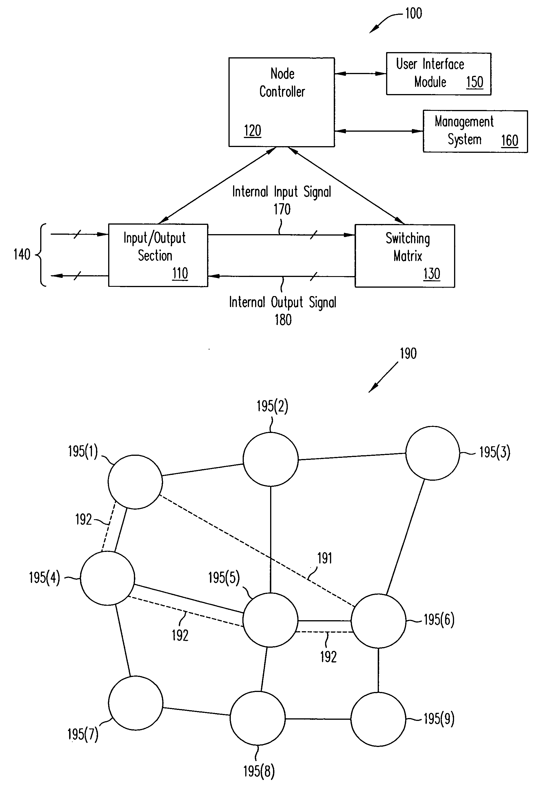
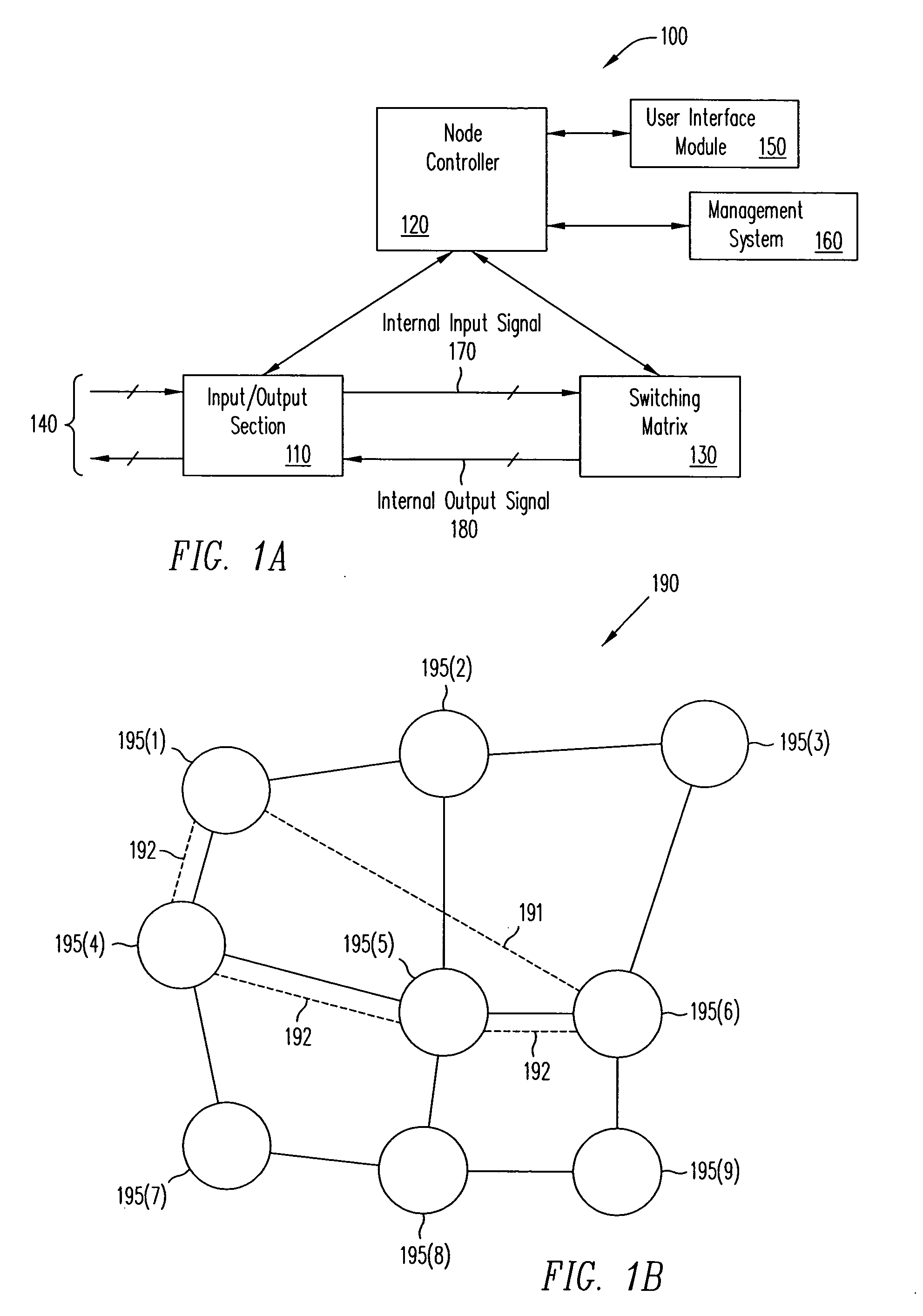
[0047]FIG. 1A illustrates a router100. Router 100 includes an input / output section 110, a node controller 120, and a switching m...


PUM


Abstract

A method is provided to allocate bandwidth from a first node to a second node in a optical network. The method begins by accepting a request from an end-user, who requests a virtual path between the first node and the second node. The first and second nodes are ones of a number of such nodes. Each one of the nodes is coupled to at least one other node by at least one of a number of optical links. The nodes and links form the optical network. The virtual path has a bandwidth requirement associated therewith. Next, the service provider determines an amount of bandwidth available between the first and the second nodes. The service provider then allocates at least a portion of the amount of bandwidth available between the first and second nodes equal to the bandwidth requirement, so long as the bandwidth requirement is not greater than the amount of bandwidth available between the first and second nodes.

Description

CROSS-REFERENCES TO RELATED APPLICATIONS[0001]The present patent application is a continuation of U.S. patent application Ser. No. 09 / 232,396, filed on Jan. 15, 1999, entitled “METHOD OF ALLOCATING BANDWIDTH IN AN OPTICAL NETWORK” and is related to U.S. patent application Ser. No. 09 / 232,395, filed on Jan. 15, 1999, entitled “A CONFIGURABLE NETWORK ROUTER,” having A. Saleh, H. M. Zadikian, Z. Baghdasarian, and V. Parsi as inventors, and U.S. patent application Ser. No. 09 / 232,397, filed on Jan. 15, 1999, entitled “A METHOD FOR ROUTING INFORMATION OVER A NETWORK,” having A. Saleh, H. M. Zadikian, J. C. Adler, Z. Baghdasarian, and V. Parsi as inventors. These related applications are assigned to, Cisco Technology, Inc. the assignee of the present invention, and are hereby incorporated by reference, in their entirety and for all purposes.BACKGROUND OF THE INVENTION[0002]1. Field of the Invention[0003]This invention relates to the field of information networks, and more particularly rel...

Claims


Application Information

Patent Timeline
Patent Type & Authority Patents(United States)
IPC IPC(8): H04L12/56H04Q11/00
CPCH04J14/0227H04J14/0294H04J14/0295H04J14/0297H04L12/5695H04L47/15H04L47/741H04L47/743H04L47/746H04L47/748H04L47/805H04L47/822H04L47/825H04L47/826H04Q11/0005H04Q11/0062H04J14/0241H04J14/0228H04J14/0282H04J14/0283H04J14/0284H04Q2011/0058H04Q2011/0081H04Q2011/0084H04Q2011/0086H04Q2011/0088H04L47/70
Inventor ZADIKIAN, HAIG MICHAELSALEH, ALI NAJIBADLER, JOHN CONLONBAGHDASARIAN, ZAREHPARSI, VAHID
Owner CISCO TECH INC
Learn More