Fixing apparatus and image forming apparatus

Active Publication Date: 2005-09-27
CANON KK
View PDF19 Cites 9 Cited by
  • Summary
  • Abstract
  • Description
  • Claims
  • Application Information

AI Technical Summary

Benefits of technology

[0041]According to the present invention, in the fixing apparatus in which the heat generating means is provided in the fixing film having the elastic layer, at least one temperature detecting means for the fixing film and at least one temperature detecting means for the heat generating means are provided, and the temperature of the fixing film is controlled by controlling the heat generating means on the basis of the detection temperature of the fixing film detected by the temperature detecting means, whereby it is possible to responsively control the fixing film and also secure safety in an abnormal state.
[0042]Moreover, the controlling to the heat generating means based on the detection temperature of the heat generating means by the temperature detecting means and the controlling to the heat generating means based on the det

Problems solved by technology

However, in the heat roller fixing apparatus having such an elastic layer as this, a heat capacity of the heat roller itself is large, whereby there is a problem that a time (warmup time) necessary to increase the temperature of the fixing roller 102 up to the temperature suitable for fixing the toner image is prolonged.
Moreover, there is a problem that costs of the fixing member increase.
However, when the fixing apparatus 201 which uses the fixing film 203 having no elastic layer is used as the fixing apparatus of a color image forming apparatus, the surface of the fixing film 203 cannot cope with the surface of the transfer material P, unevenness due to existence/inexistence of a toner layer, unevenness of the toner layer itself and the like.
That is, the heat from the fixing member is well transmitted to the convex portion which is sufficiently in contact with the fixing member, but it is hard to transmit the heat from the fixing member to the concave portion as compared with the convex portion.
For this reason, when the fixing member does not include any elastic layer, uneven brightness on the image obtained after the image fixing was performed becomes noticeable, thereby degrading image quality.
Also, in a case where an OHP sheet is used as the transfer material, image quality deteriorates due to poor permeability when the image obtained after the image fixing was performed is projected.
Moreover, when a silicon oil or the like is applied to the fixing member having no elastic layer so that the heat is well transferred entirely to the concave and convex portions of the transfer material and the unfixed toner image, a problem that costs increase occurs, and also a problem that the image obtained after the image fixing was performed and the transfer material are sticky with the oil occurs.
1) The heat conductivity of the sili

Method used


Image

  • Fixing apparatus and image forming apparatus
  • Fixing apparatus and image forming apparatus
  • Fixing apparatus and image forming apparatus

Examples


Example

(Embodiment 1)

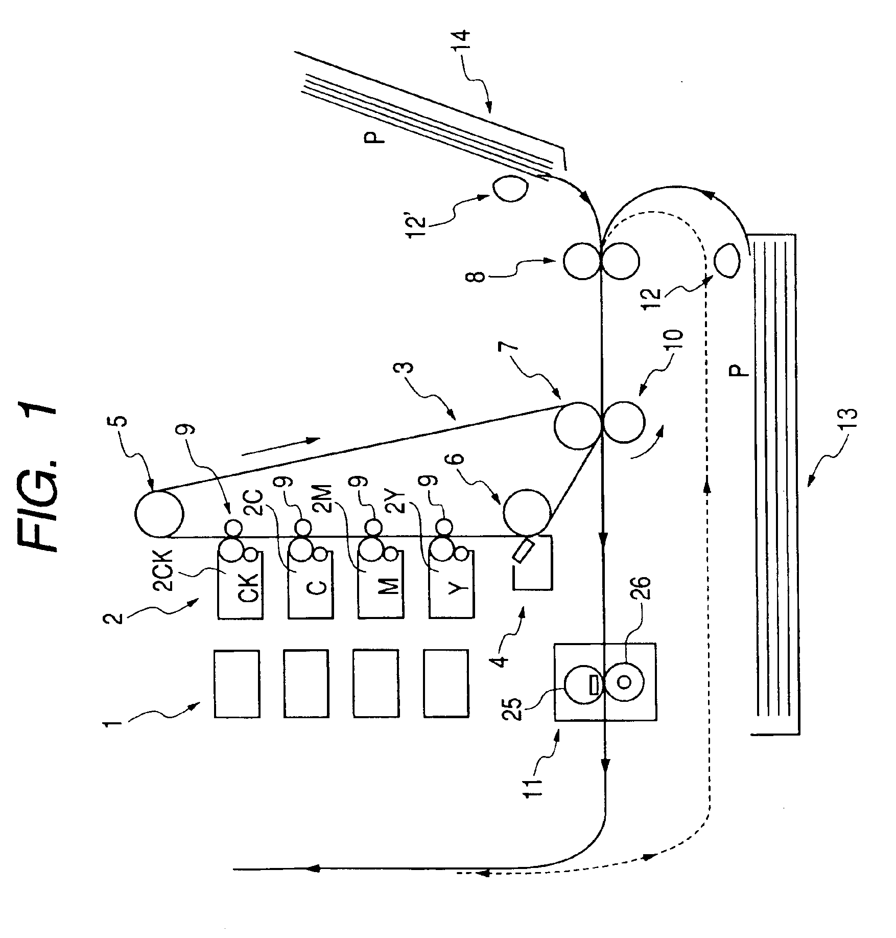
[0059]FIG. 1 is a schematic structural diagram showing a color image forming apparatus to which a fixing apparatus of the present invention is applied. In the present embodiment, an in-line color image forming apparatus of an intermediate transfer body system is used, and an automatic double-side mechanism (not shown) acting as a known automatic double-side transporting means is provided after the fixing apparatus, whereby a transfer material to which image fixing has been once performed can be automatically inverted and again transported for refeeding.

[0060]In FIG. 1, the portion indicated by the solid lines denotes a transporting path of the transfer material on which the image fixing to the first surface of the transfer material is performed in an automatic double-side image forming mode, and the portion indicated by the dotted lines denotes a reverse transporting path of the transfer material on which the image fixing to the second surface of the transfer material ...

Example

(Embodiment 2)

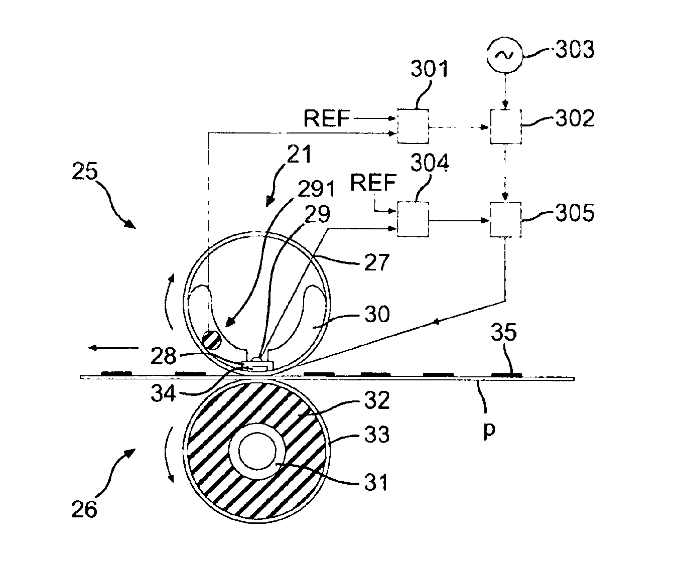
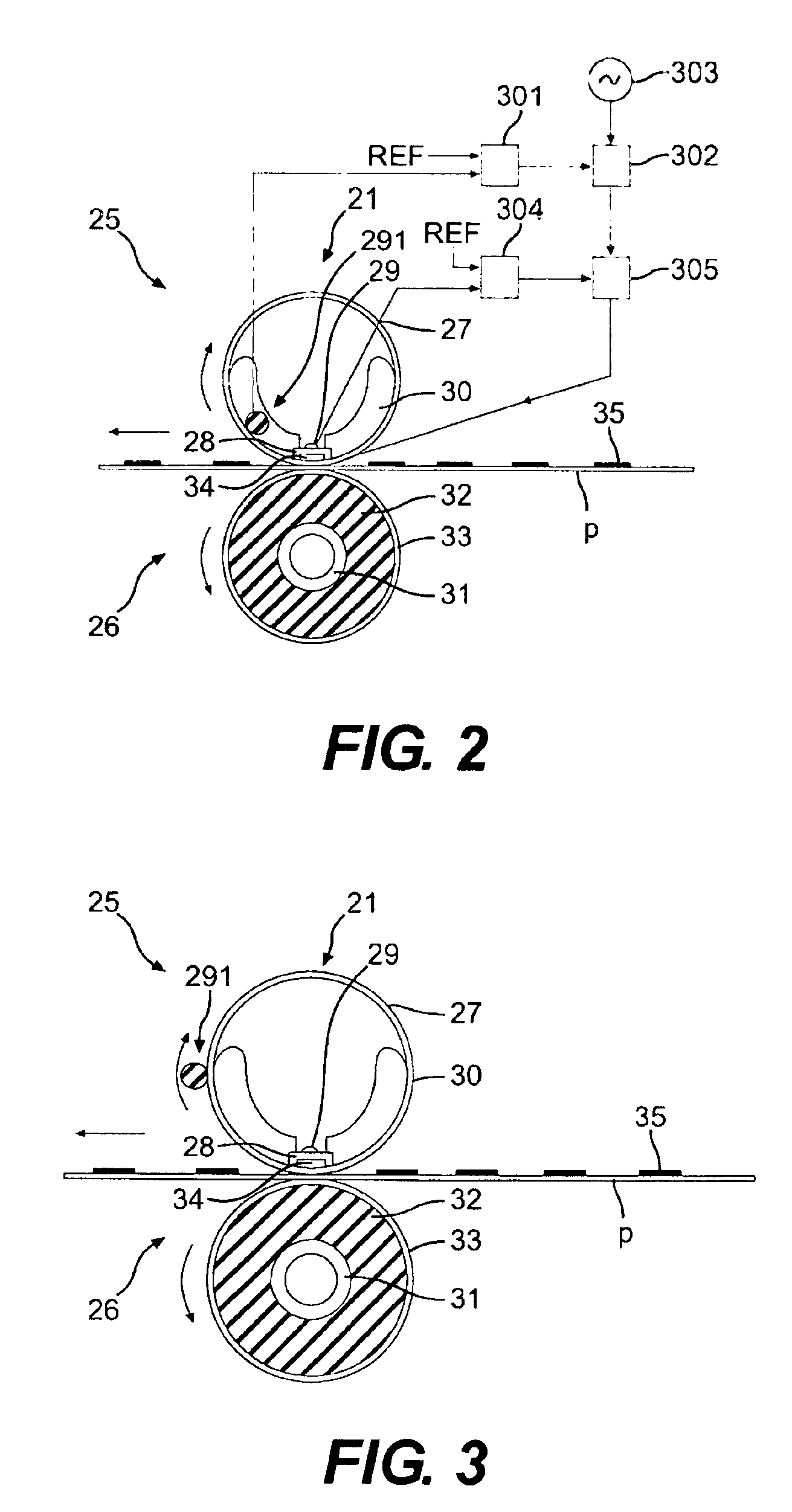
[0113]The embodiment 2 of the present invention will be explained hereinafter. FIG. 3 is a schematic structural diagram showing a fixing apparatus according to the embodiment 2 of the present invention. In FIG. 3, the explanation will be omitted in regard to the portions same as those in the embodiment 1. In the embodiment 2, unlike the embodiment 1, a temperature detecting means 291 of a fixing film is set to be in contact with the outer surface of the fixing film.

[0114]A graph 4 in FIG. 9 shows a temperature drop of the fixing film and the like according to the embodiment 2. In the present embodiment, because the temperature detecting means of the fixing film is set to be in contact with the surface of the fixing film, the temperature drop of the fixing film by a transfer material P can be responsively detected as compared with the embodiment 1, whereby the temperature drop of the fixing film can be suppressed within the limits of about 5° C.

Example

(Embodiment 3)

[0115]The embodiment 3 of the present invention will be explained hereinafter. A fixing apparatus to be used in the present embodiment is the same as that used in the embodiment 1, whereby the explanation thereof will be omitted.

[0116]The present embodiment is different from the above embodiments in the point that the control of preventing the temperature of a ceramic heater from exceeding a certain temperature based on the temperature detected by a temperature detecting means being in contact with the ceramic heater is combined with ordinary temperature control only when printing starts, thereby preventing excessive temperature rise of the ceramic heater.

[0117]FIG. 10 is a flow chart for explaining a control method of the fixing apparatus according to the present embodiment. It should be noted that, in this control method, the ceramic heater is driven by feedback control based on the result detected by such a fixing film temperature detecting means.

[0118]In the presen...


PUM


Abstract

A fixing apparatus in which at least one temperature detecting element for detecting a temperature of a fixing film and at least one temperature detecting element for detecting a temperature of a heat generating element are included, and which controls the heat generating element on the basis of the temperature of the fixing film detected by the temperature detecting element and thus achieves temperature controlling of the fixing film, and an image forming apparatus to which the fixing apparatus is applied are disclosed.

Description

BACKGROUND OF THE INVENTION[0001]1. Field of the Invention[0002]The present invention relates to a fixing apparatus in which a fixing film having an elastic layer and a heat generating means provided so as to affect a non-fixing surface of the fixing film are included, and an image forming apparatus such as a copying machine, a laser beam printer (hereinafter, called LBP), a printer, a facsimile machine, a microfilm reader printer, a recorder or the like to which the fixing apparatus in question is applied.[0003]More particularly, the present invention relates to a fixing apparatus of a method for (1) forming and bearing an unfixed toner image corresponding to target image information on the surface of a transfer material (paper, print paper, transfer material sheet, electrofax sheet, electrostatic recording sheet, OHP sheet, glossy paper, glossy film, or the like) in a direct transfer method or an indirect transfer method with user of toner made of a heat melting resin or the like ...

Claims


Application Information

Patent Timeline
IPC IPC(8): G03G15/20H05B3/00
CPCG03G15/2039G03G2215/2035G03G15/2053G03G2215/2074
Inventor SAITO, TORUANDO, ATSUTOSHISUZUKI, TAKEHIKOAKIZUKI, TOMOO
Owner CANON KK
Why Eureka
Try Eureka