
Control technique for a communication system

Inactive Publication Date: 2005-09-27
ALCATEL-LUCENT USA INC +1
View PDF20 Cites 47 Cited by
  • Summary
  • Abstract
  • Description
  • Claims
  • Application Information

AI Technical Summary

Benefits of technology

[0010]The present invention provides a novel communication management technique for systems including microcells, which reduces the problems described above with conventional communication systems including microcells. In particular, the principle of the present invention solves the above-identified problem by co-locating the microcell antenna with the macrocell antenna.
[0012]Other cost savings may be realized by co-locating and possibly sharing other common macrocell and microcell basestation components.

Problems solved by technology

Continuing growth in wireless telecommunications usage is placing increasing stress on the capacity of cellular systems which provide wireless telecom service.
Although the introduction of digital cellular systems has increased potential system capacity, these increases alone may be insufficient to satisfy added demand for capacity.
Microcells suffer from a series of problems, including an increased sensitivity to traffic variations, interference between microcells, and difficulty in anticipating traffic intensities.
As the capacity of cellular systems has increased, cell sizes have decreased, in some networks to as small as 0.5 km radius, such that controlling co-channel interface has become a major problem.
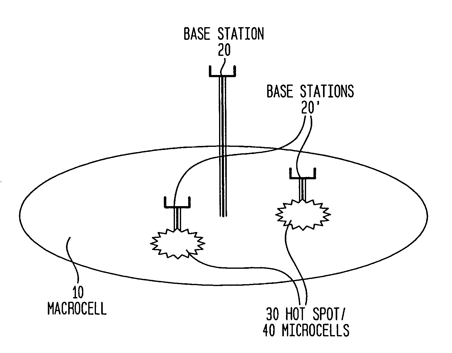
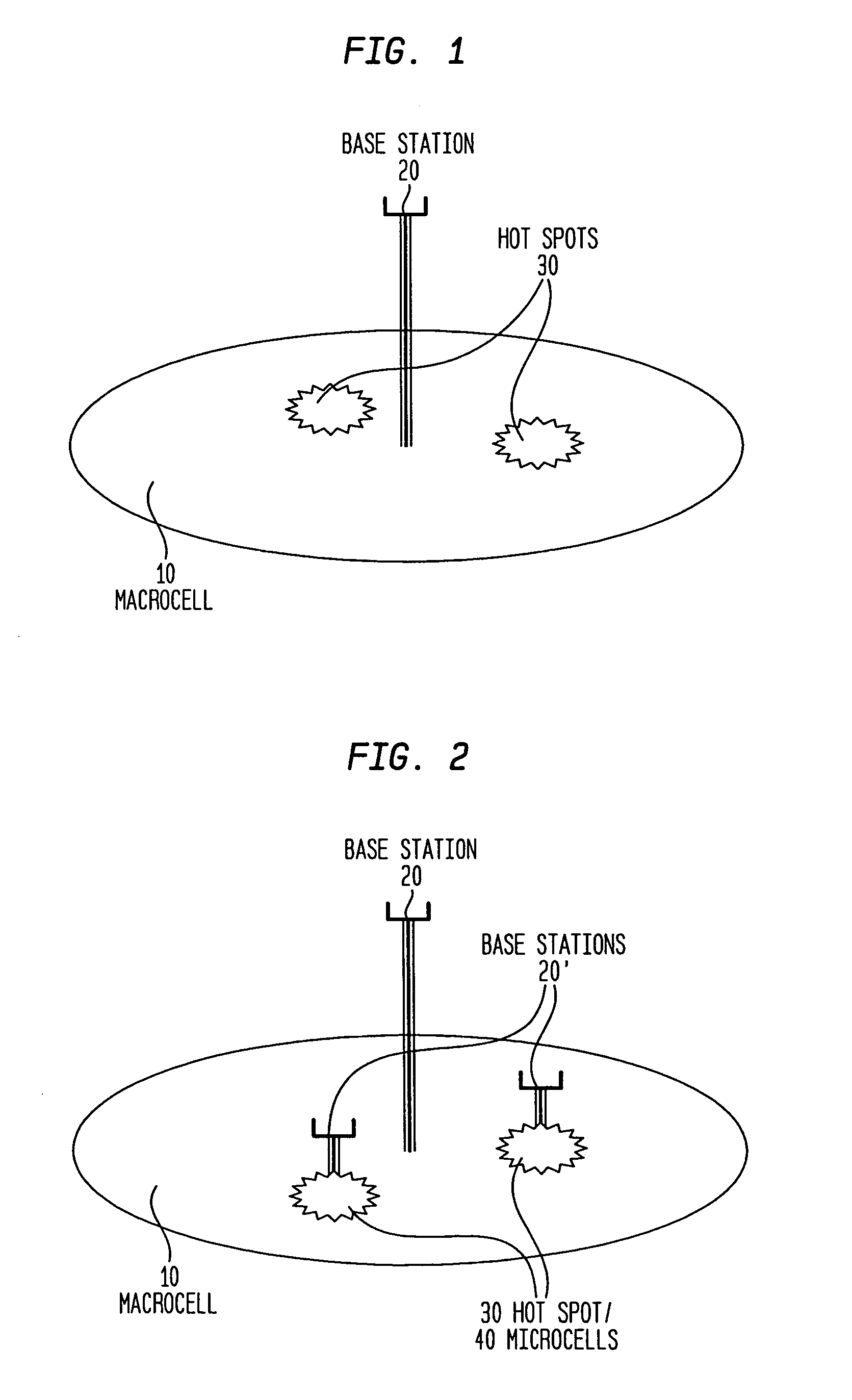
Such a solution requires installing basestations 20′ in each hot spot coverage area, which is costly.

Method used


Image

  • Control technique for a communication system
  • Control technique for a communication system
  • Control technique for a communication system

Examples


Embodiment Construction

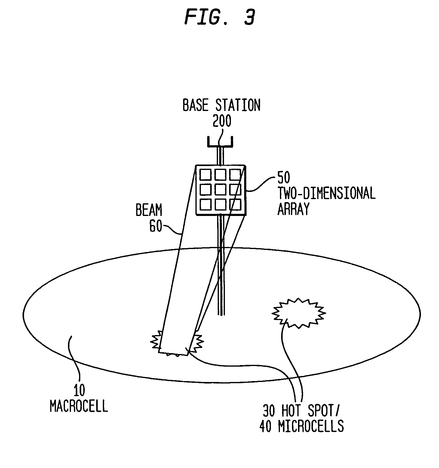
[0024]FIG. 3 illustrates the present invention in one exemplary embodiment. As illustrated in FIG. 3, macrocell 10 is served by basestation 200. In order to handle two hot spots 30 with relatively dense concentration of mobile users, the present invention identifies microcells 40 at the location of each of the hot spots 30. A two-dimensional array 50 is provided at the same location as the basestation 200 for each of the identified hot spots 30 / microcells 40. For clarity, FIG. 3 only illustrates one of the two-dimensional arrays 50. Each two-dimensional array 50 performs three-dimensional beamforming to steer a microcell 40 to a desired location, namely, a hot spot 30. Each two-dimensional array 50 is steerable in both the horizontal and vertical directions.

[0025]FIG. 4 illustrates the relationship of the two-dimensional array 50 with the base station 200. In particular, FIG. 4 illustrates at least two antenna elements 22, at least two radio frequency (RF) modules 24, at least two a...


PUM


Abstract

A control technique for a communication system in which a microcell base station is co-located with a macrocell base station. The microcell base station tracks hot spots as they move within the macrocell. The microcell base station may utilize a two-dimensional (2-D) antenna array, which is co-located with the macro cell antenna. The two-dimensional antenna is steerable in both the horizontal and vertical directions. The size of the microcell coverage area depends upon the distance from the cell site antenna as well as the dimensionality of the array, which determines the angular spread of the beam. Filter tap weights may be adjusted to point the beam to any desired location in the macrocell. The orthogonality between the macrocell and the microcell may be obtained either in the frequency domain or in the code domain, depending upon the system in which it is implemented.

Description

BACKGROUND OF THE INVENTION[0001]1. Field of the Invention[0002]The present invention relates to a control technique for a communication system, and more particularly, to a control technique for a wireless communication system.[0003]2. Description of the Related Art[0004]Continuing growth in wireless telecommunications usage is placing increasing stress on the capacity of cellular systems which provide wireless telecom service. The limited frequency spectrum available for cellular communications demands that cellular systems have increased network capacity and adaptability to various communications traffic situations. Although the introduction of digital cellular systems has increased potential system capacity, these increases alone may be insufficient to satisfy added demand for capacity. Other measures to increase system capacity, such as decreasing the size of cells in metropolitan areas, may be necessary to meet growing demand.[0005]It is known in the prior art that localized mi...

Claims


Application Information

Patent Timeline
IPC IPC(8): H04Q7/30H04Q7/36H04B7/26H04W16/32H04W88/08H01Q3/26
CPCH04W16/32
Inventor MUJTABA, SYED AONGABARA, THADDEUS JOHN
Owner ALCATEL-LUCENT USA INC
Learn More