Reliable outdoor instrument cooling system

a cooling system and reliable technology, applied in the field of enclosures for electronic equipment, can solve problems such as the degradation of accuracy and resolution of measurement systems, the components of measurement systems being subjected to temperatures in excess of their preferred operating temperature range, and the low signal-to-noise ratio of measurement systems

Active Publication Date: 2005-10-04
WEATHERFORD TECH HLDG LLC
View PDF11 Cites 27 Cited by
  • Summary
  • Abstract
  • Description
  • Claims
  • Application Information

AI Technical Summary

Problems solved by technology

Often, such control panels are located in remote locations of the earth and subjected to extreme temperatures, which may subject the components to temperatures in excess of their preferred operating temperature range.
Further, some components used in measurement systems, especially those that have very low signal to noise ratios (e.g. capacitive based systems), may suffer degradation in accuracy and resolution due to changing ambient temperatures at the front end of their signal conditioning.
Heat generated within the panels may be passively removed, but as the ambient (outside) temperature increases, cooling by passive means becomes less effective.
However, neither approach is satisfactory if the temperature of the device must be below the outside air temperature.
However, cooling systems utilizing refrigerators and fans contain many moving parts and are, therefore, subject to mechanical failure.
For example, refrigerating compressor components are subject to mechanical failure and typically require frequent maintenance, However, remotely located control panels are generally required to operate essentially unattended for long periods of time and frequent maintenance is inconvenient and expensive, particularly if production operations are interrupted.
Additionally, cooling systems using refrigerators require substantial power to drive the compressor and typically require a reliable external source of electrical power (e.g., line AC service), which is often not available in remote locations.

Method used


Image

  • Reliable outdoor instrument cooling system
  • Reliable outdoor instrument cooling system
  • Reliable outdoor instrument cooling system

Examples


Embodiment Construction

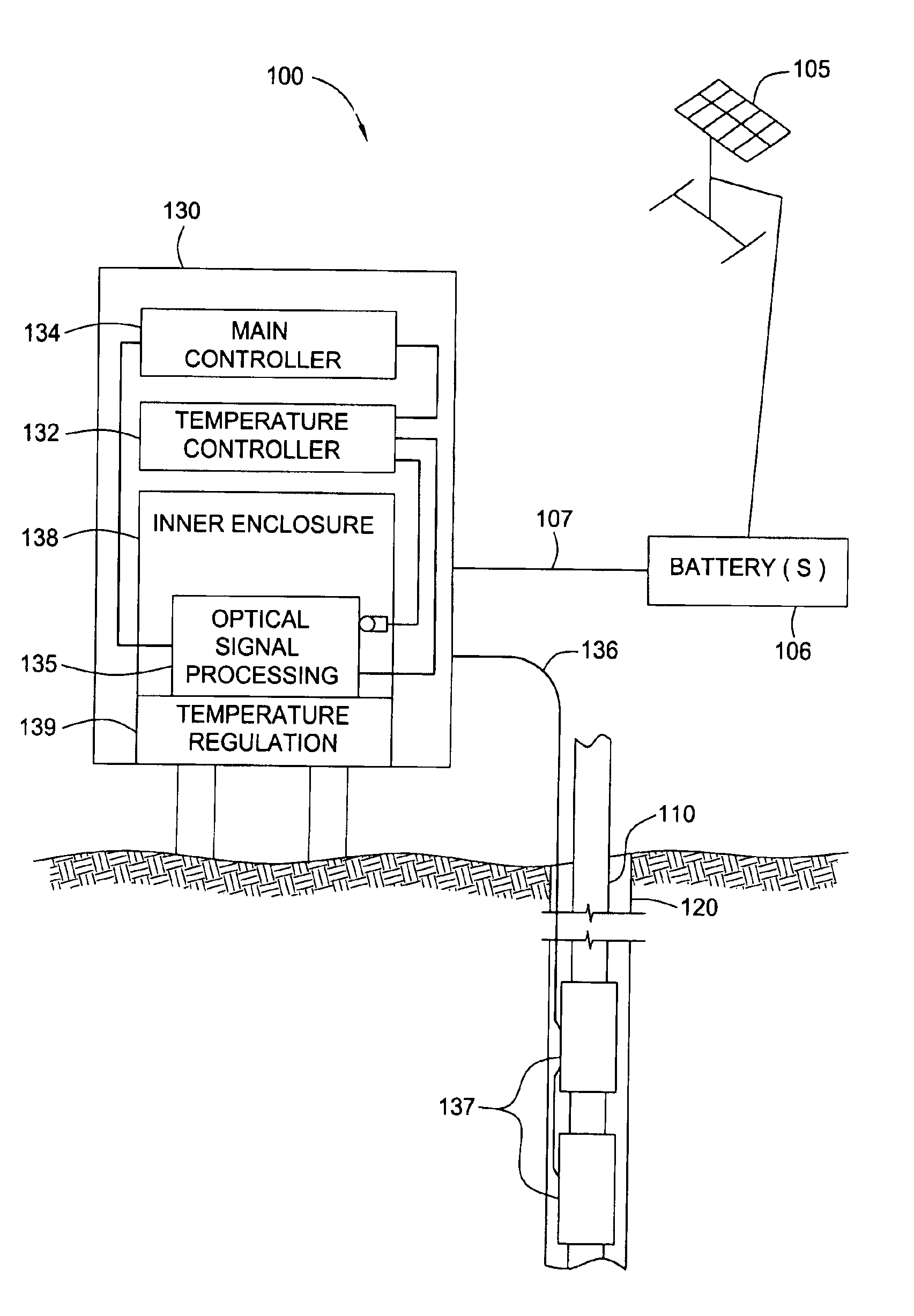
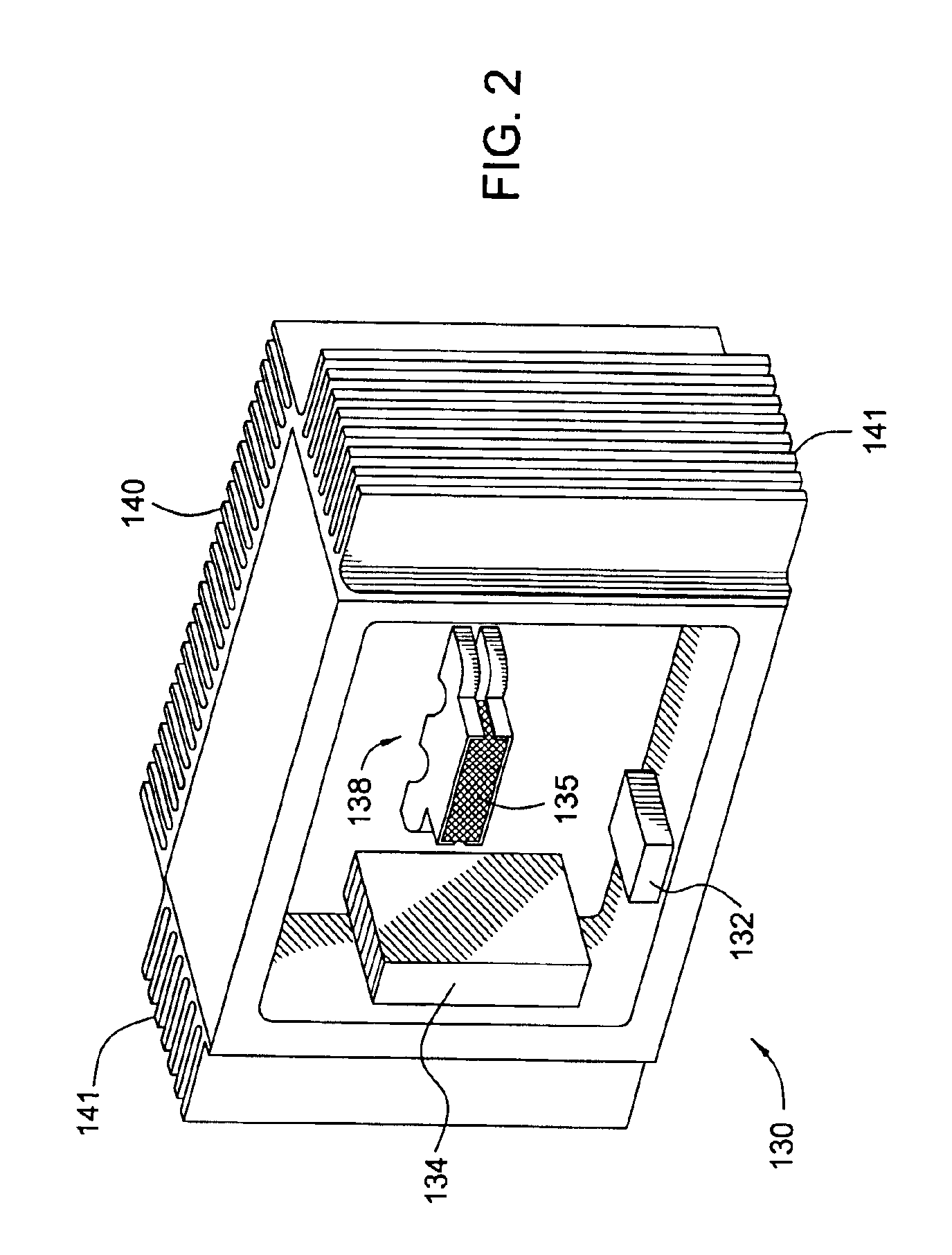
[0021]The present invention generally provides methods, apparatus and systems for controlling the temperature in an enclosure suitable for housing temperature sensitive components. For some embodiments, cooling systems of the present invention may utilize thermoelectric cooling (TEC) devices. TEC devices are particularly appropriate for this application because they contain no moving parts and require little maintenance relative to compressor based refrigerators and cooling systems utilizing fans. For some embodiments, the cooling systems may also include a self contained power source operable in remote locations of the earth (e.g., locations without reliable electrical power).

[0022]Embodiments of the present invention may be utilized to an advantage to maintain the operating temperature of virtually any type temperature-sensitive equipment, such as analog electronic components, high speed digital electronics, components with very low signal to noise ratios_or any other type of comp...


PUM


Abstract

A method, system, and apparatus for controlling the temperature within a remotely located enclosure that contains temperature sensitive equipment is provided. For some embodiments, the system includes an array of thermoelectric cooling (TEC) devices that act as an active cooling device and an active heating device. The system may also include a temperature controller that receives signals from a temperature sensor located at or near the temperature sensitive equipment. The controller may be configured to supply DC power to the thermoelectric coupling devices based on the output signal of the temperature sensor. The polarity of the DC power can be reversed by the controller in order to cause the thermoelectric device to heat or to cool the enclosure. The system also contains a passive cooling device. The system includes an independent electrical power source with a battery and solar cell to supply power to the temperature control devices and the equipment contained in the enclosure.

Description

BACKGROUND OF THE INVENTION[0001]1. Field of the Invention[0002]The present invention relates to an enclosure for housing electronic equipment and, more particularly, to a temperature-controlled enclosure for housing remotely located temperature sensitive equipment, such as optical signal processing components for monitoring downhole parameters in oil wells.[0003]2. Description of the Related Art[0004]Electronic equipment produces heat when operated and, when the equipment is located in an environment with extreme ambient temperatures, some means of controlling the temperature of the equipment is typically required. Certain electronic equipment, such as opto-electronic components used in optical signal processing are especially sensitive to temperature variation and require an operating temperature in a relatively narrow range in order to function properly. In the oil production industry, such optical signal processing components, located in a control panel at a wellbore surface, ar...

Claims


Application Information

Patent Timeline
Patent Type & Authority Patents(United States)
IPC IPC(8): F25B21/02F25B27/00G05D23/19H01L35/00
CPCF25B21/02F25B27/002G05D23/1919H01L35/00F25B2321/0212F25B2700/2104F25D2700/16H10N10/00
Inventor GRISHAM, JOHN N.MEADOWS, MICHAEL M.PERRY, LESLIE WAYNESALLWASSER, ALAN J.
Owner WEATHERFORD TECH HLDG LLC
Why Eureka
Try Eureka