
Electrically conductive tire and apparatus and process for extruding elements which have been made conductive

a technology of electric conductive tires and extruders, which is applied in the direction of tyre parts, textiles and papermaking, and tyres using treads, which can solve the problems of accumulating static electricity to a greater or lesser extent, giving the occupant of the vehicle an unpleasant electric shock, and achieving the effect of dissipating electrostatic charges and reducing costs

Inactive Publication Date: 2005-10-04
MICHELIN & CO CIE GEN DES ESTAB MICHELIN
View PDF27 Cites 44 Cited by
  • Summary
  • Abstract
  • Description
  • Claims
  • Application Information

AI Technical Summary

Benefits of technology

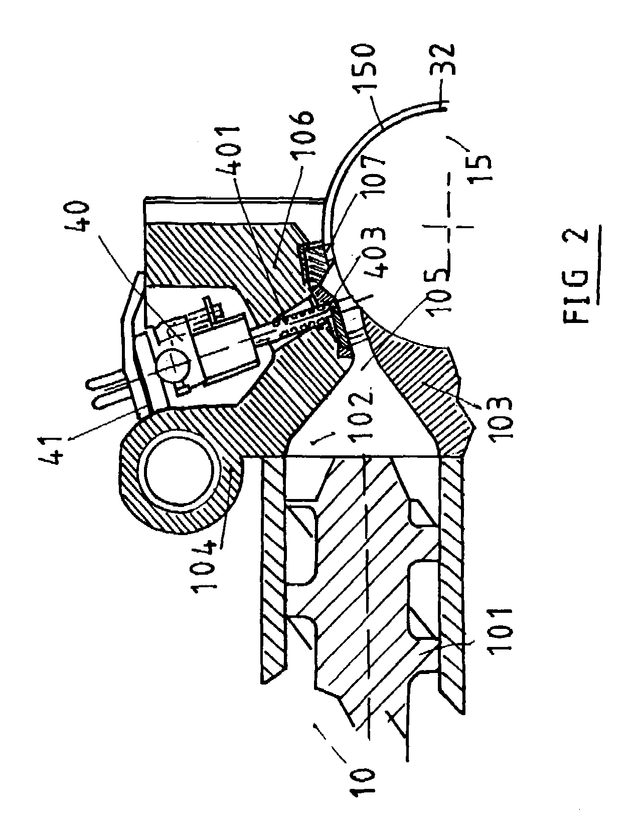
[0028]Said nozzle is characterized in that it comprises an annular part for bearing on and attachment to the die of the micro-extruder with the attachment elements necessary for fixing, a hollow cylindrical feed chamber, either straight or bent, having on its cylindrical surface an extrusion orifice, through which is extruded the conductive rubber material, and which occupies substantially all the height of said nozzle, and the cross-section of which has a shape adapted to the desired section of the conductive insert: In this apparatus of the second type, the extrusion nozzle is advantageously provided with a die which is mobile in translation along an axis substantially perpendicular to the axis of the roller, and making it possible, under the action of the pressure of the conductive mix which passes through it, to manufacture products of different thicknesses, while guaranteeing, during their manufacture, a minimum distance between the end of the nozzle and the roller of the main extruder.

Problems solved by technology

Although this solution makes it possible to obtain the best compromise between all the very contradictory properties mentioned above, it has however proved that, depending on the vehicles, tires using a tread comprising silica as main reinforcing filler have the disadvantage of accumulating static electricity to a greater or lesser extent, this being formed by friction of the tire on the road during travel of the vehicle due to the lack of electrical conductivity of the silica.
The static electricity thus built up in a tire, when certain specific conditions are combined, is capable of giving the occupant of a vehicle an unpleasant electric shock when he has cause to touch the body of the vehicle.
It may also be the cause, depending on the type of ground and the vehicle, of poor operation of the onboard radio owing to the interference which it produces.
This problem of buildup of static electricity in a tire and of the majority of the disadvantages linked thereto is a very old one, and occurred even in the days when the reinforcing filler used was carbon black.
Although such a solution is perfectly viable for a tire comprising a tread formed of a single non-conductive mix, for example, a tread for a passenger vehicle, the same does not apply in the case of a tire comprising a plurality of layers of rubber mixes above the crown reinforcement and layers of rubber between the crown reinforcement and the carcass reinforcement, as is the case for any tire liable to travel at a high stabilized operating temperature, such as heavy vehicles or high-speed vehicles.
Although industrially satisfactory, said method requires additional laying of product and involves additional production costs.
Furthermore, the mechanical properties of the rubber compositions before vulcanizations are very poor, and the uncured rubber mix may be in the form of an extremely soft paste, or conversely an extremely hard agglomerate.
Whatever the manner of working such mixes, it is difficult perfectly to control the geometry of the semi-finished product, the assembly of the two non-vulcanized parts of the tread: the concordance and alignment between the respective traces of the two sets of striping on the contact wall between the two parts cause great development difficulties, the solution of two sets of circular striping being unable to be considered as structurally optimized and industrially viable, both from the point of view of cost and of the performance obtained.

Method used


Image

  • Electrically conductive tire and apparatus and process for extruding elements which have been made conductive
  • Electrically conductive tire and apparatus and process for extruding elements which have been made conductive
  • Electrically conductive tire and apparatus and process for extruding elements which have been made conductive

Examples


Embodiment Construction

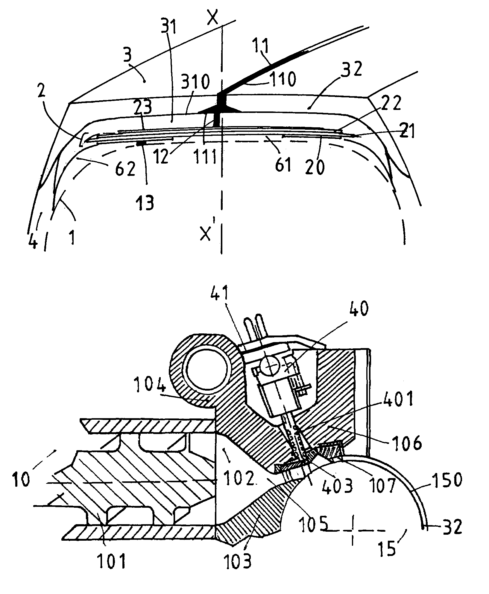
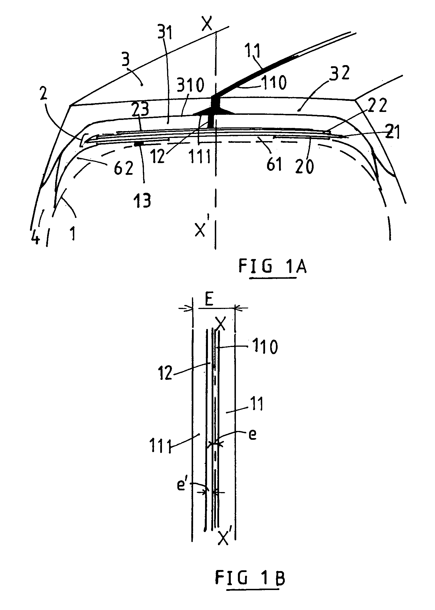
[0035]The tire of dimension 315 / 80 R 22.5, which is designed to have a low rolling resistance, comprises a carcass reinforcement 1 composed of a metal ply formed of inextensible metal cables coated in a rubber calendering mix, which is rendered conductive of electrostatic charges by means of a carbon black commonly used as a reinforcing filler in mixes. Said carcass reinforcement 1 is, as is known, anchored to at least one bead wire within each bead to form an upturn (not shown). Within said carcass reinforcement 1 there are the conventional reinforcement layers, and the so-called inner layers formed of mixes which are generally impermeable to the known inflation gases. The end(s) of this (these) inner layer(s) is (are) generally covered by the axially inner part of the protective layer of the bead (not shown), a wear layer, the axially outer part of which bears on the mounting rim, said layer generally having a very high content of carbon black filler, and therefore being highly co...


PUM

PropertyMeasurementUnit
Pressureaaaaaaaaaa
Electrical conductivityaaaaaaaaaa
Electrical conductoraaaaaaaaaa

Abstract

A tire having a tread composed of two non-conductive layers, each layer containing a circumferential insert of conductive mix, the inserts having a wider interface at the interface of the two layers. An apparatus for extruding a layer, provided with a conductive insert, including a main extruder for extruding a non-vulcanized, non-conductive layer, and a micro-extruder having an extrusion head, provided at its end with a nozzle, for extruding a conductive insert in the layer.

Description

[0001]This is a continuation of PCT / EP99 / 01044, Filed Feb. 17, 1999.BACKGROUND OF THE INVENTION[0002]The subject of the present invention is a tire composed of a plurality of mixes comprising as majority filler a non-conductive filler such as silica, or mixes having a low content of black filler, at least one of these mixes being the tread. It relates more particularly to a tire which may exhibit not insignificant internal temperature increases during travel, such as a tire intended, for example, to bear heavy loads. It also relates to a process for making such a tire, and an apparatus for carrying out such a process.[0003]Since environmental problems are becoming ever more crucial, and savings in terms of fuel and the fight against the pollution produced by motor vehicles have become a priority, one of the aims of tire manufacturers is to produce a tire having all of the following: very low rolling resistance, excellent adhesion both on dry ground and on wet or snow-covered or icy ...

Claims


Application Information

Patent Timeline
IPC IPC(8): B29C47/06B29C47/12B29D30/52B60C1/00B60C19/00B60C19/08B29C48/07B29C48/30
CPCB29C47/064B29C47/12B29C47/32B29D30/52B60C19/08B60C11/005B29C47/0019B29D2030/526B29K2019/00B29K2995/0005B29K2995/0007Y10S152/02B29C48/07B29C48/19B29C48/20B29C48/35
Inventor CALVAR, DIDIERNICOLAS, SERGEBARDY, DANIEL
Owner MICHELIN & CO CIE GEN DES ESTAB MICHELIN
Learn More