
Multi-wheel vehicle

a multi-wheel vehicle and wheel technology, applied in the field of vehicles, can solve the problems of vehicle laterally compactness, difficult steering of the vehicle, and long time-consuming adjustment of shipment, and achieve the effect of not affecting the turning of the vehicl

Inactive Publication Date: 2005-10-04
KANZAKI KOKYUKOKI MFG
View PDF163 Cites 51 Cited by
  • Summary
  • Abstract
  • Description
  • Claims
  • Application Information

AI Technical Summary

Benefits of technology

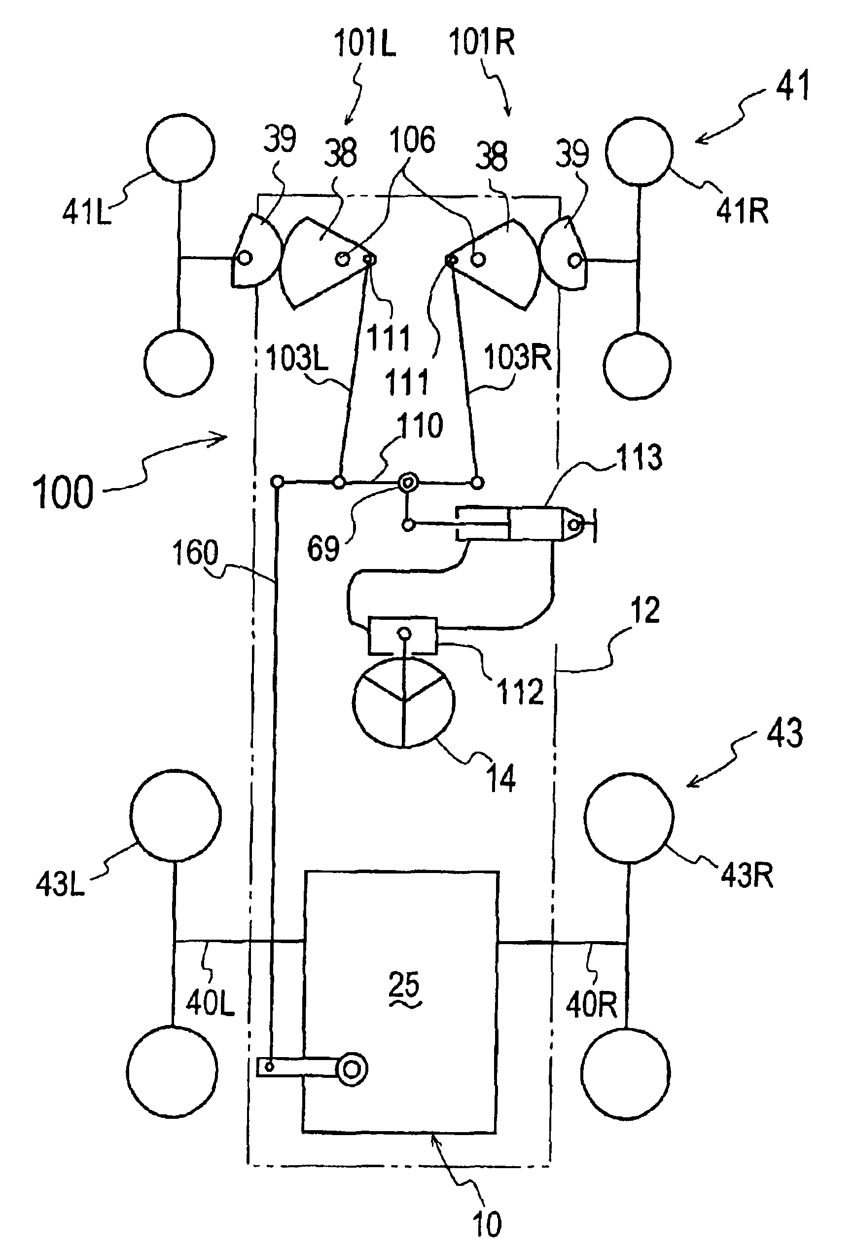
[0010]An object of the present invention is to provide a vehicle having a pair of running-driving wheels controlled by manipulation of a steering operation device such as a steering wheel so as to rotate differentially for turning the vehicle right or left, and having a pair of steerable running wheels which are laterally turned by manipulation of the steering operation device, wherein the lateral turning angles of the steerable running wheels are amplified so as not to hinder the turning of the vehicle caused by the differential rotation of the running-driving wheels.
[0012]The steering mechanism turns the pair of steerable running wheels laterally according to manipulation of the steering operation device for turning the vehicle right or left so as to make the turning angle of the steerable running wheel serving as the inside wheel greater than the turning angle of the other steerable running wheel serving as an outside wheel disposed at outside of the turning vehicle. Furthermore, the steering mechanism may turn the pair of steerable running wheels laterally according to increase of the manipulated degree of the steering operation device so as to reduce an increasing rate of turning angle of the steerable running wheels serving as the outside wheel in relation to a unit of the manipulated degree of the steering operation device.

Problems solved by technology

The above-said vehicle, however, could not travel straight-forward unless the output rotations of left and right HSTs completely coincided with each other, adjustments in shipment took much time, and parts and assembly errors had to be diminished so as to improve accuracy.
Also, when there was a difference between the capacities of hydraulic pumps and motors, left or right turning feeling of the vehicle was different, resulting in that the vehicle was very hard to steer.
Also, when both the hydrostatic pumps and motors are arranged in a longitudinal line, the vehicle becomes laterally compact.
If the vehicle is provided with a caster in addition to the pair of running wheels, it can turn in a small circle, however, cornering on a rough road or a slope becomes unstable.
However, the steerable running wheels restrict the reduction of cornering circle.
It is impossible for the steerable running wheels to have such a small cornering circle that can be ensured by casters.
Especially, it is further hard for the vehicle to turn on a determined radius circle steadily when the vehicle has a plurality of running wheels arranged in a longitudinal direction so as to be made larger in whole length.

Method used


Image

  • Multi-wheel vehicle
  • Multi-wheel vehicle
  • Multi-wheel vehicle

Examples


Embodiment Construction

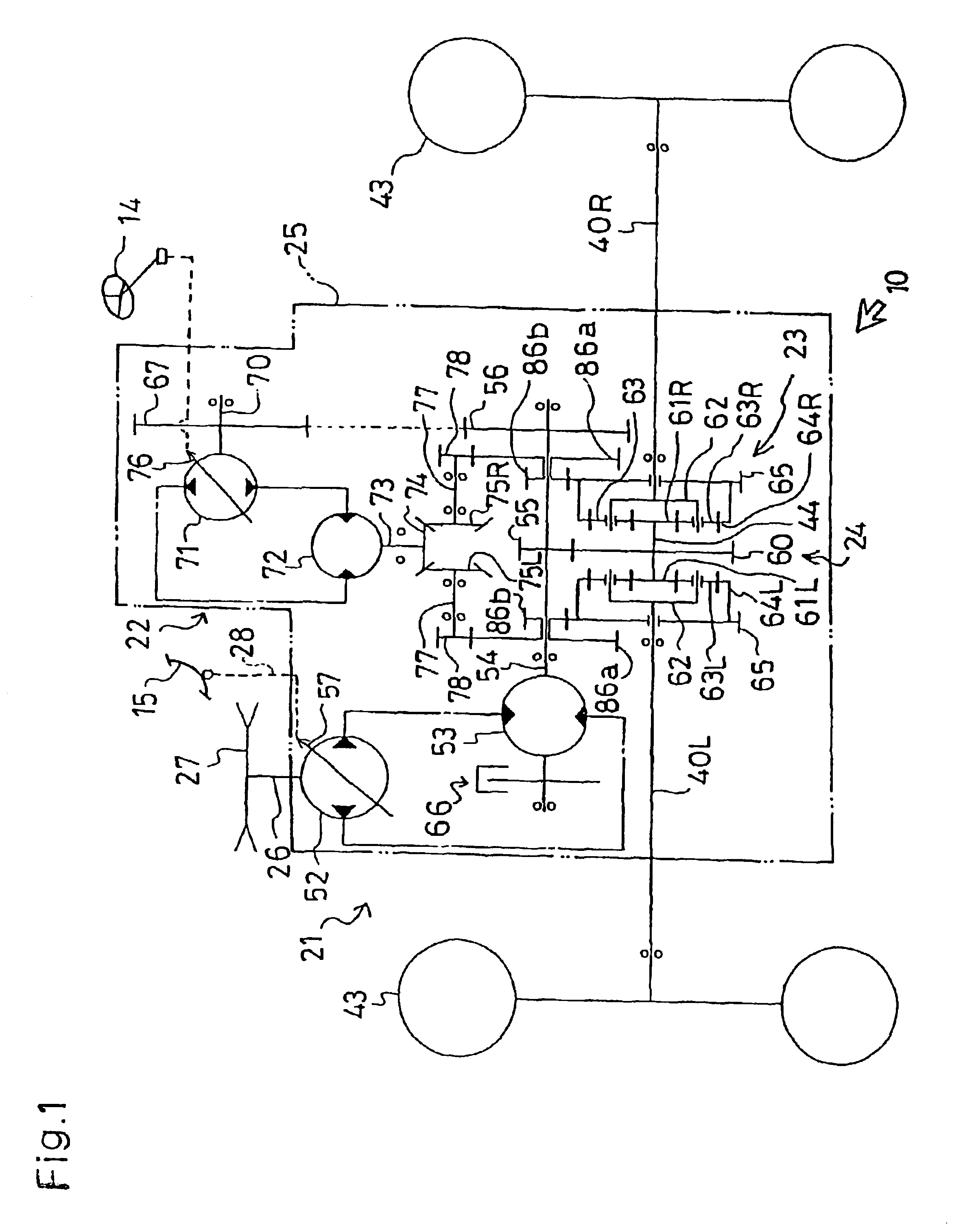
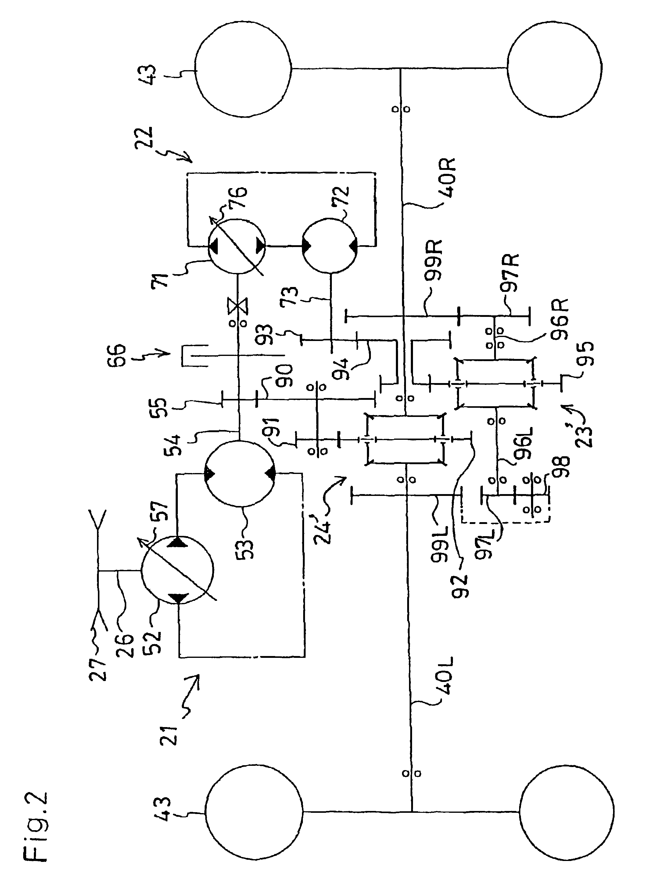
[0072]An axle driving / steering unit 10 of the present invention can make its left and right running-driving wheels different in their rotary speeds that a vehicle using it turns leftward and rightward. Driving / steering unit 10 comprises a first running hydrostatic transmission (to be herein after called “a main driving HST”) 21 including a hydraulic pump and motor fluidly connected with each other, a second steering hydrostatic transmission (to be herein after called “a steering HST”) 22 including a hydraulic pump and motor fluidly connected with each other, a steering differential unit (a second differential unit) 23 for steering the vehicle, and a running differential unit (first differential unit) 24 for running-driving the vehicle. Differential units 23 and 24 are either of a type as a combination of planetary gears and bevel gears or of a type as a combination of a pair of differential gears.

[0073]Referring to FIG. 1 showing axle driving / steering unit 10 using planetary gears a...


PUM


Abstract

A vehicle comprises a steering operation device, a pair of running-driving wheels, which differentially drive when the steering operation device is manipulated, a pair of steerable running wheels interlocking with the steering operation device, and a steering mechanism interposed between the steering operation device and the pair of running-driving wheels. The steering mechanism includes a pair of drive gears interlocking with the steering operation device and a pair of follower gears interlocking with the respective steerable running wheels. The drive gears mesh with the respective follower gears so as to control lateral turning of the respective steerable running wheels. A gear radius of the drive gear may be greater than that of the follower gear meshing with it. A gear ratio between the mutually meshing drive and follower gears may be variable. The lateral turning centers of both the steerable running wheels may coincide with each other, and further coincide with a lateral turning center of the vehicle body caused by differential rotation of the running-driving wheels.

Description

REFERENCE TO RELATED APPLICATION[0001]This application is a Continuation-in-Part of application Ser. No. 09 / 820,673, filed Mar. 30, 2001 now U.S. Pat. No. 6,554,085, which is a continuation-in-part of application Ser. No. 09 / 372,747, filed Aug. 11, 1999 now U.S. Pat. No. 6,336,513 the disclosures of which are incorporated herein in their entirety by reference.BACKGROUND OF THE INVENTION[0002]1. Field of the Invention[0003]The present invention relates to a vehicle comprising a steering operation means, a pair of running-driving wheels which are differentially driven when the steering operation means is operated for cornering, and a pair of steerable running wheels interlocking with the steering operation means.[0004]2. Background Art[0005]Conventionally, technology where a pair of hydrostatic transmissions (HSTs) are laterally connected, driving axles project laterally from respective HSTs, running-driving wheels are fixed to the outer ends of both axles, wherein movable swash plate...

Claims


Application Information

Patent Timeline
IPC IPC(8): B62D9/00B62D11/00B62D11/18B62D11/06B62D11/24
CPCB62D7/09B62D7/142B62D7/1509B62D9/00B62D11/18B62D11/183B62D11/24
Inventor IRIKURA, KOJI
Owner KANZAKI KOKYUKOKI MFG
Learn More