Electropolishing of metallic interconnects
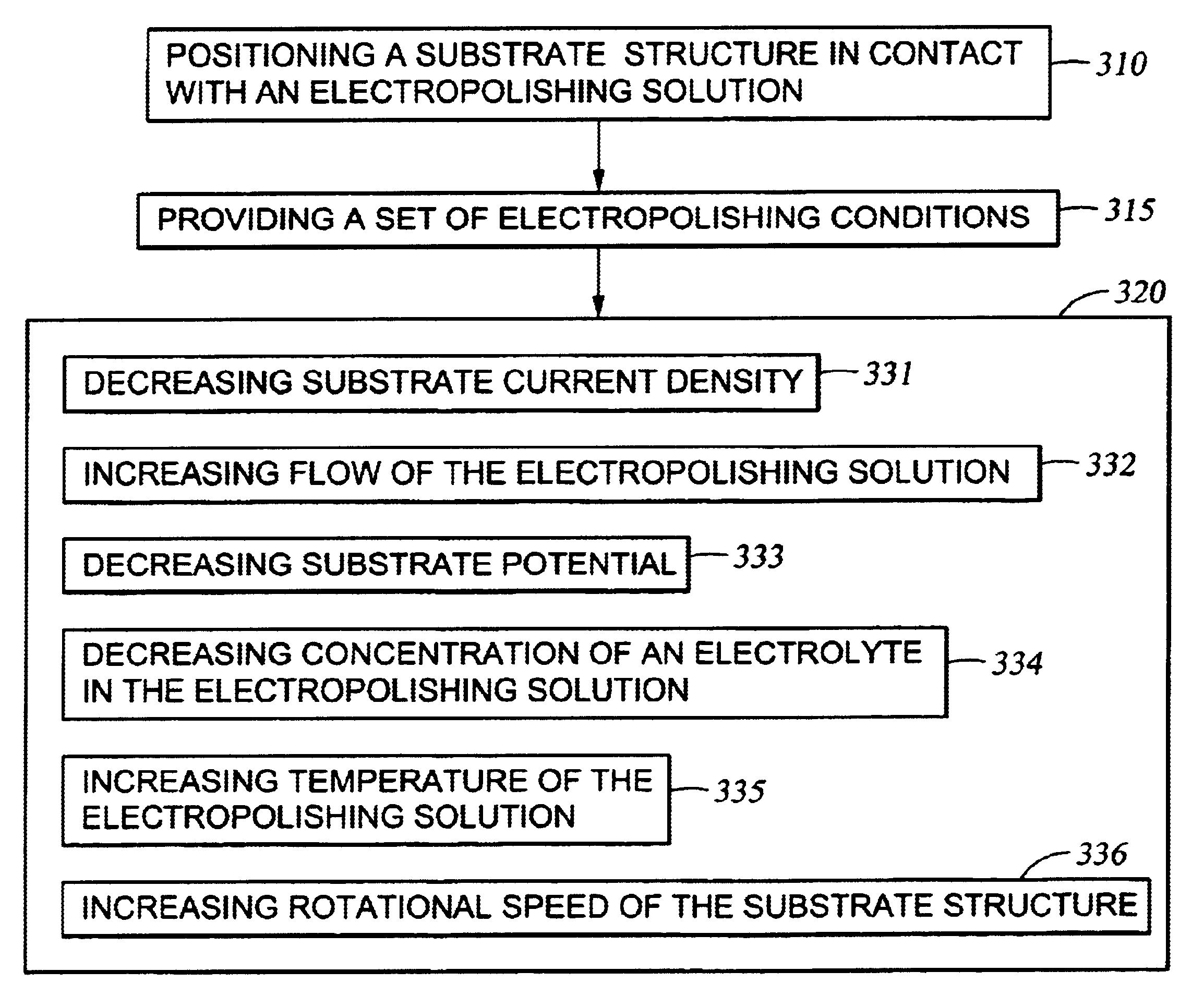
a technology of electropolishing and metallic interconnects, which is applied in the field of electropolishing of metallic interconnects, can solve the problems of long process time for copper removal, affecting the mechanical integrity of low-k dielectric materials, and insufficient reduction of step height, so as to reduce the current density of substrates, increase the flow of electropolishing solution, and reduce the potential of substrates
- Summary
- Abstract
- Description
- Claims
- Application Information
AI Technical Summary
Benefits of technology
Problems solved by technology
Method used
Image

Examples
example 2
[0061]Substrate 2 was electropolished at a rotational speed of about 10 rpm. A polarization curve was obtained by measuring the substrate current density as a function of the substrate potential in reference to an SCE reference electrode. The polarization curve was obtained by utilizing a current scan with a controlled current power supply. The results are shown in Table 2.
[0062]As shown in Table 2, initially, the current density rises with an increase in substrate potential from about 0.0 V to about 0.4 V. From a substrate potential from about 0.4 V to about 1.3 V, the current density reaches a plateau at a substantially constant level. From a substrate potential above about 1.3 V, the substrate current density begins to rise with substrate potential.
[0063]Not wishing to be bound by any particular theory unless set forth in the claims, it is believed that the plateau in the substrate current density at a substrate potential from about 0.4 V to about 1.3 V is indicative of the prese...
example 3
[0065]Various substrates were electropolished at different constant substrate current densities at an electropolishing solution flow rate of about 0.15 GPM. The substrates were not rotated (i.e., rotational speed of 0 rpm). Substrate 3 was electropolished at a constant substrate current density of about 19 mA / cm2. Substrate 4 was electropolished at a constant substrate current density of about 25.5 mA / cm2. Substrate 5 was electropolished at a constant substrate current density of about 31.8 mA / cm2. Substrate 6 was electropolished at a constant substrate current density of about 47.7 mA / cm2. Substrate 7 was electropolished at a constant substrate current density of 63.6 mA / cm2. The substrate potential was measured as a function of time at the various constant current substrate densities. The results are reflected in Table 3.
[0066]As shown in Table 3, Substrate 3 showed a substantially constant substrate potential over time. Substrates 4-7 showed an initial low substrate potential bet...
example 4
[0070]Various substrates were electropolished at different rotational speeds. Each substrate was electropolished at a constant substrate current density of about 25 mA / cm2. Substrate 8 was not rotated (0 rpm). Substrate 9 was rotated at 10 rpm. Substrate 10 was rotated at about 15 rpm. Substrate 11 was rotated at about 25 rpm. Substrate 12 was rotated at about 50 rpm. The substrate potentials of the substrates were measured as a function of time. The results are reflected in Table 4.
[0071]As shown in Table 4, Substrates 8-12 showed an initial low substrate potential between about 0.3 V and about 0.5 V. Then, over a short period of time relative to each substrate, the substrate potential increased to a high value between about 1.4 V and about 1.9 V depending on the rotational speed. This surge in substrate potential occurred earlier in time for lower rotational speeds.
[0072]Not wishing to be bound by any particular theory unless set forth in the claims, it is believed that during the...
PUM
| Property | Measurement | Unit |
|---|---|---|
| Temperature | aaaaa | aaaaa |
| Temperature | aaaaa | aaaaa |
| Temperature | aaaaa | aaaaa |
Abstract
Description
Claims
Application Information
 - R&D Engineer
- R&D Manager
- IP Professional
- Industry Leading Data Capabilities
- Powerful AI technology
- Patent DNA Extraction
Browse by: Latest US Patents, China's latest patents, Technical Efficacy Thesaurus, Application Domain, Technology Topic.
© 2024 PatSnap. All rights reserved.Legal|Privacy policy|Modern Slavery Act Transparency Statement|Sitemap