
Method and device for filtering liquids, especially drinks

a technology for filtering liquids and drinks, applied in gravity filters, loose filtering materials, cartridge filters, etc., to achieve the effect of reducing investment, operating and maintenance costs, and ensuring the highest quality

Inactive Publication Date: 2005-10-04
E BEGEROW GMBH
View PDF10 Cites 8 Cited by
  • Summary
  • Abstract
  • Description
  • Claims
  • Application Information

AI Technical Summary

Benefits of technology

[0008]Objects of the present invention are to provide a process and a device for filtering liquids, beverages in particular, which are fully automated to the greatest extent possible, have the lowest possible investment, operating, and maintenance costs, and yield a filtrate of the highest possible quality, and in the case of wine filtration a filtrate free of yeast.
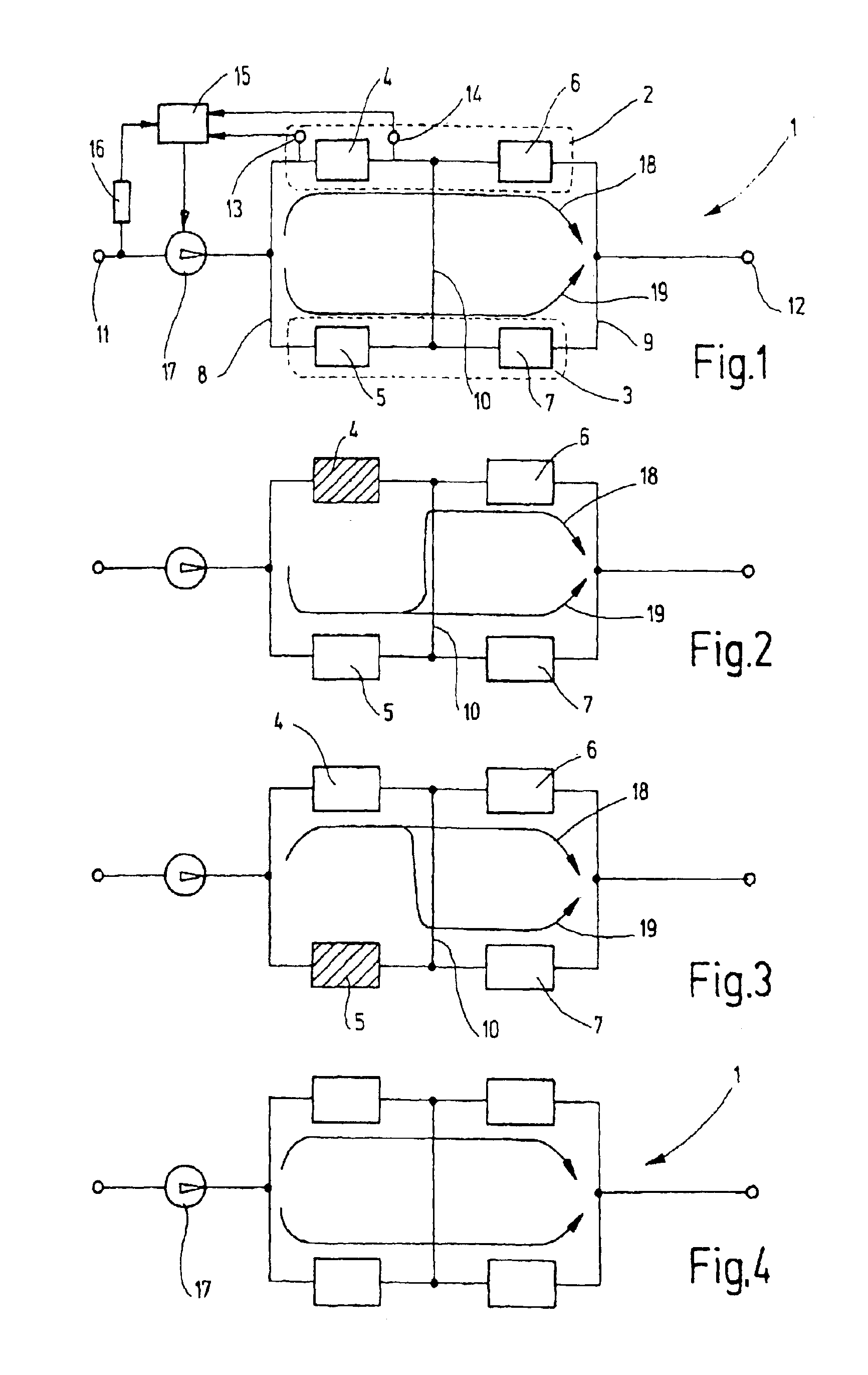
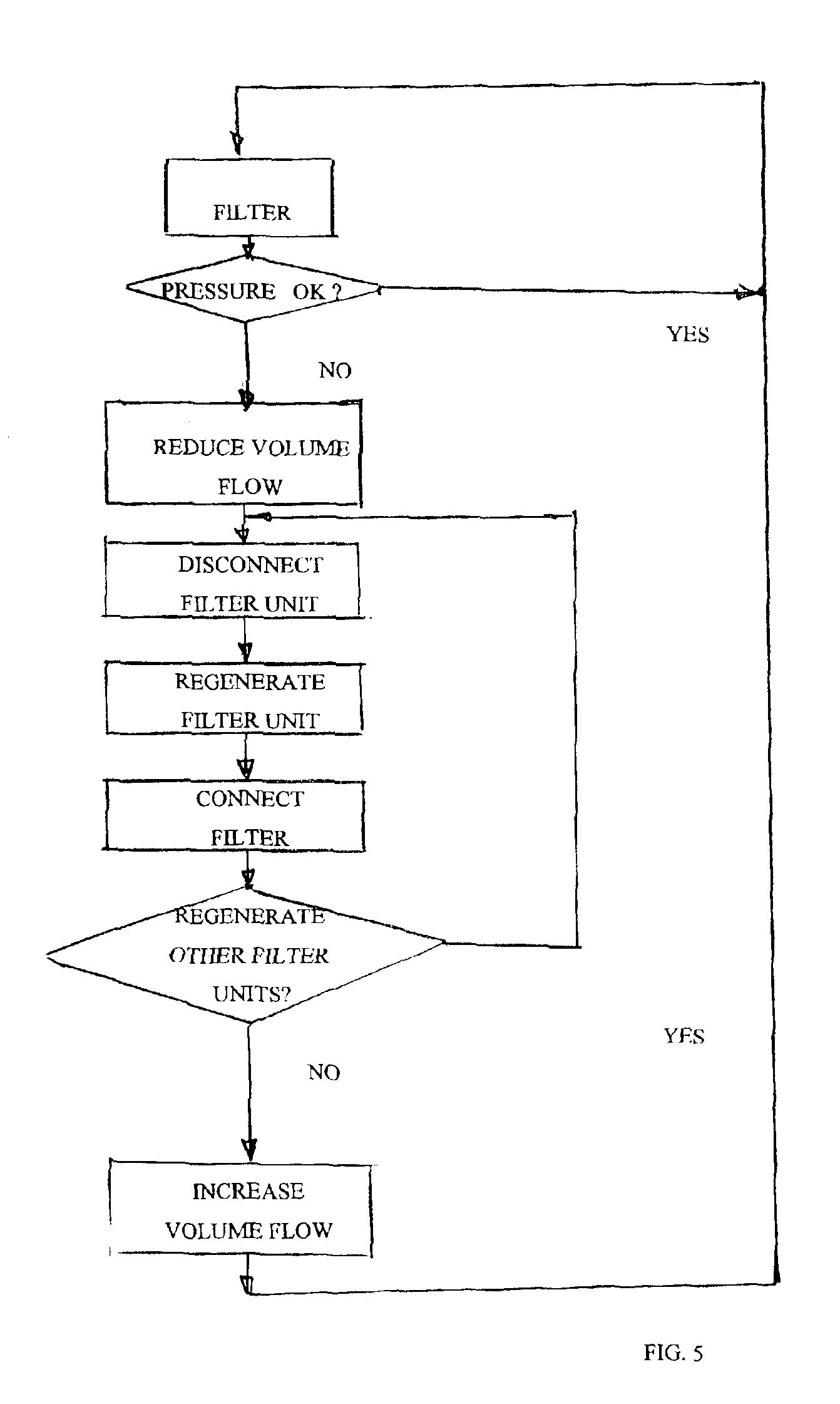
[0010]A filter unit generally has a filter housing and a filter element, a filter cartridge for example. An increased volume flow would be applied to the filter units remaining in operation as a result of removal of the filter unit to be regenerated. This increased volume flow could lead to problems, as for example, blockage of used filter cartridges. For this reason, the volume flow is reduced before or during removal of the filter cartridge to be regenerated. A negative effect exerted by the filter units remaining in operation is thereby prevented. This process may be fully automatically operated by use of a suitable control device, one which has the pressure differentials occurring on the filter units, for example, as input variables. The volume flow entering the device is adjusted preferably by a pump controlled by the control unit.

Problems solved by technology

This increased volume flow could lead to problems, as for example, blockage of used filter cartridges.

Method used


Image

  • Method and device for filtering liquids, especially drinks
  • Method and device for filtering liquids, especially drinks
  • Method and device for filtering liquids, especially drinks

Examples


Embodiment Construction

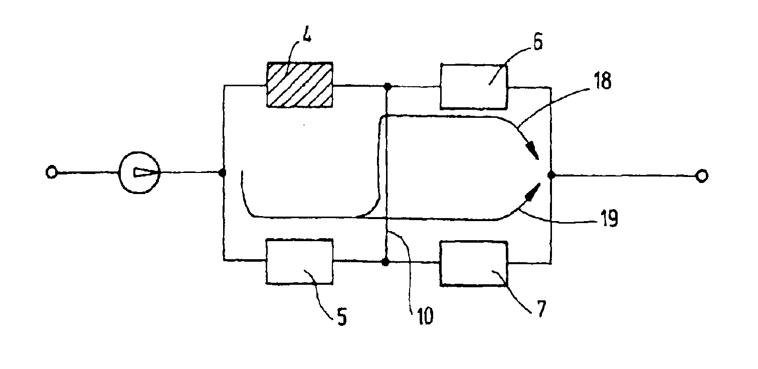
[0021]FIGS. 1 to 4 illustrate in diagrammatic form various operating states of the process of the present invention for filtering liquids, particularly beverages, with a filter of filtration device 1. 1 the exemplary embodiment illustrated, the filter device has two filter lines 2, 3. Each filter line 2, 3 has of a preliminary filter or filter unit 4, 5 and an end filter or filter unit 6, 7, respectively. The filter device 1 may analogously have other filter lines and / or each filter line other filter units. The preliminary filters 4, 5 are connected on the inlet side to a collective inlet line 8. The end filters 6, 7 are on the outlet side connected to a collective outlet line 9. The preliminary filters 4, 5 of the first and second filter lines 2, 3 may be interconnected by way of a transverse line 10.

[0022]For the sake of clarity, the accompanying valves for engaging or disengaging the connecting lines between inlet 11 and the preliminary filters 4, 5, the end filters 6, 7, and the...


PUM

PropertyMeasurementUnit
temperatureaaaaaaaaaa
output voltageaaaaaaaaaa
pressureaaaaaaaaaa

Abstract

A method for filtering liquids, especially drinks, is by a filtering device having at least two filter lines. Each filter line has at least one filter unit with at least one preliminary filter and one terminal filter which can be connected to or disconnected from the respective filter line independently of each other and which can also be independently regenerated. The pressure differential of at least one filter unit on each filter line is measured. Once a predefinable threshold value is reached for the pressure differential, the volume flow entering the device is reduced. The associated filter unit is disconnected from the filter line. The reduced volume flow to be filtered is handled by the corresponding filter unit in the other filter line which is fluidically connected to the filter line between the respective preliminary filter and the respective terminal filter. The disconnected filter unit is regenerated. The filter unit which is purified by regeneration is subsequently reconnected to the filter line and the volume flow entering the device is increased once more.

Description

FIELD OF THE INVENTION[0001]The present invention relates to a method and a device for filtering liquids, especially drinks. The filtering device has at least two filter lines, each having at least one filter unit. The process and the device may be employed in production of at least partly fermented fruit juices, wine in particular.BACKGROUND OF THE INVENTION[0002]Solid / liquid separation operations must be performed in different process steps in the production of wine and fruit juice. This separation may be accomplished by conventional separating processes such as sedimentation, centrifuging, cake filtration, etc., or by so-called “cross-low filtration” as described in the publication by Karbachsch, M., Pototschnigg, S., and Bauer, R. “Einsatz der Cross-Flow-Filtration in der Getränkeindustrie, Kellerwirtschaft” [Use of Cross-Flow filtration in the Beverage Industry, Cellar Management]. This filtration differs from so-called “dead-end filtration” in that a shearing strain gradient a...

Claims


Application Information

Patent Timeline
Patent Type & Authority Patents(United States)
IPC IPC(8): B01D37/04B01D37/00
CPCB01D37/046
Inventor BRETT, ELKEHEINEMEYER, CARSTENTESCH, RALF
Owner E BEGEROW GMBH
Learn More