Rotary electric machine and a method of producing the same
a technology of rotary electric machine and rotary motor, which is applied in the direction of grinding machine, manufacturing tool, stator/rotor body manufacturing, etc., can solve the problems of productivity drop, cost increment, productivity drop, etc., and achieve low noise, low cost, and good performance
- Summary
- Abstract
- Description
- Claims
- Application Information
AI Technical Summary
Benefits of technology
Problems solved by technology
Method used
Image
Examples
embodiment 1
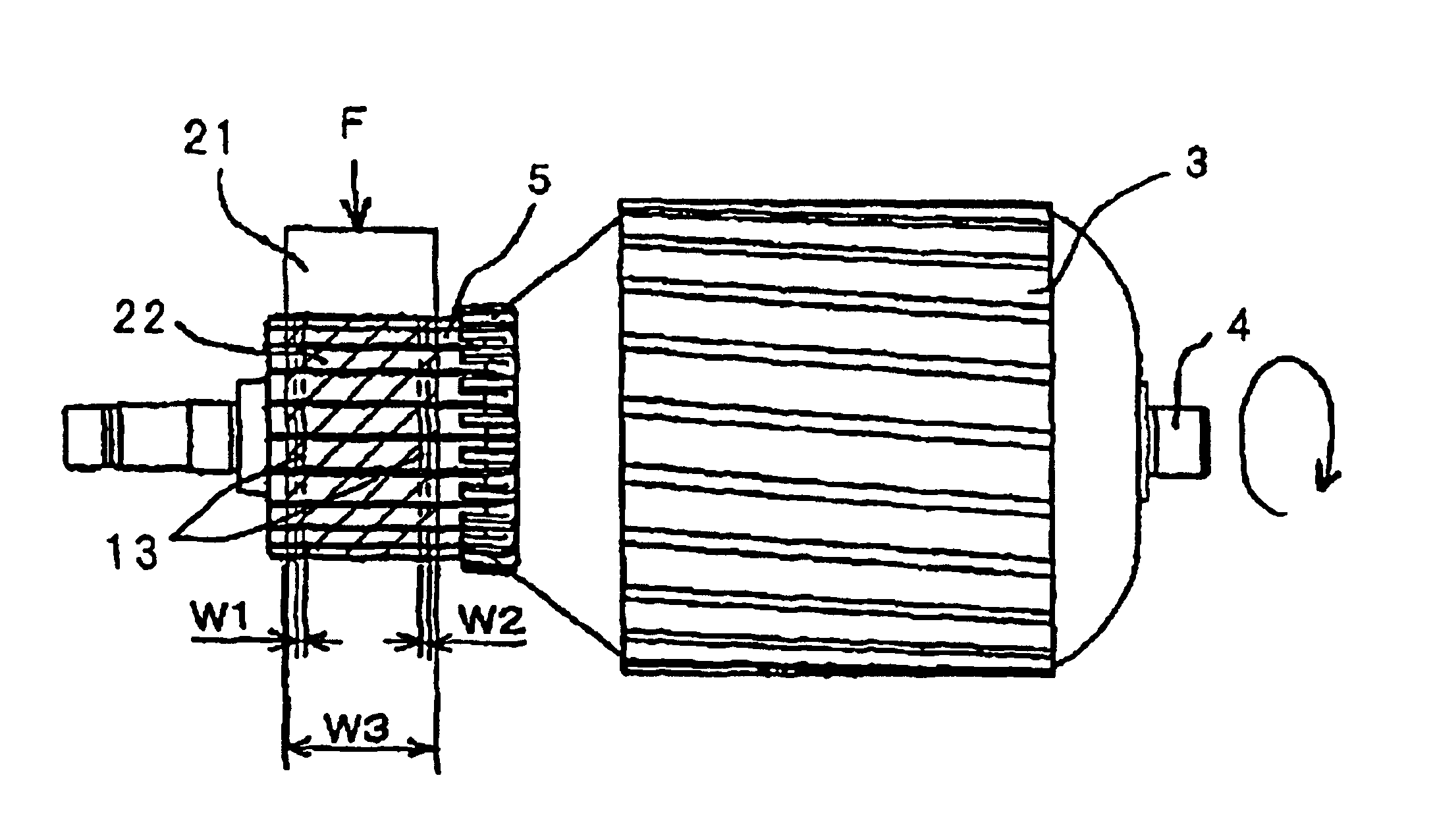
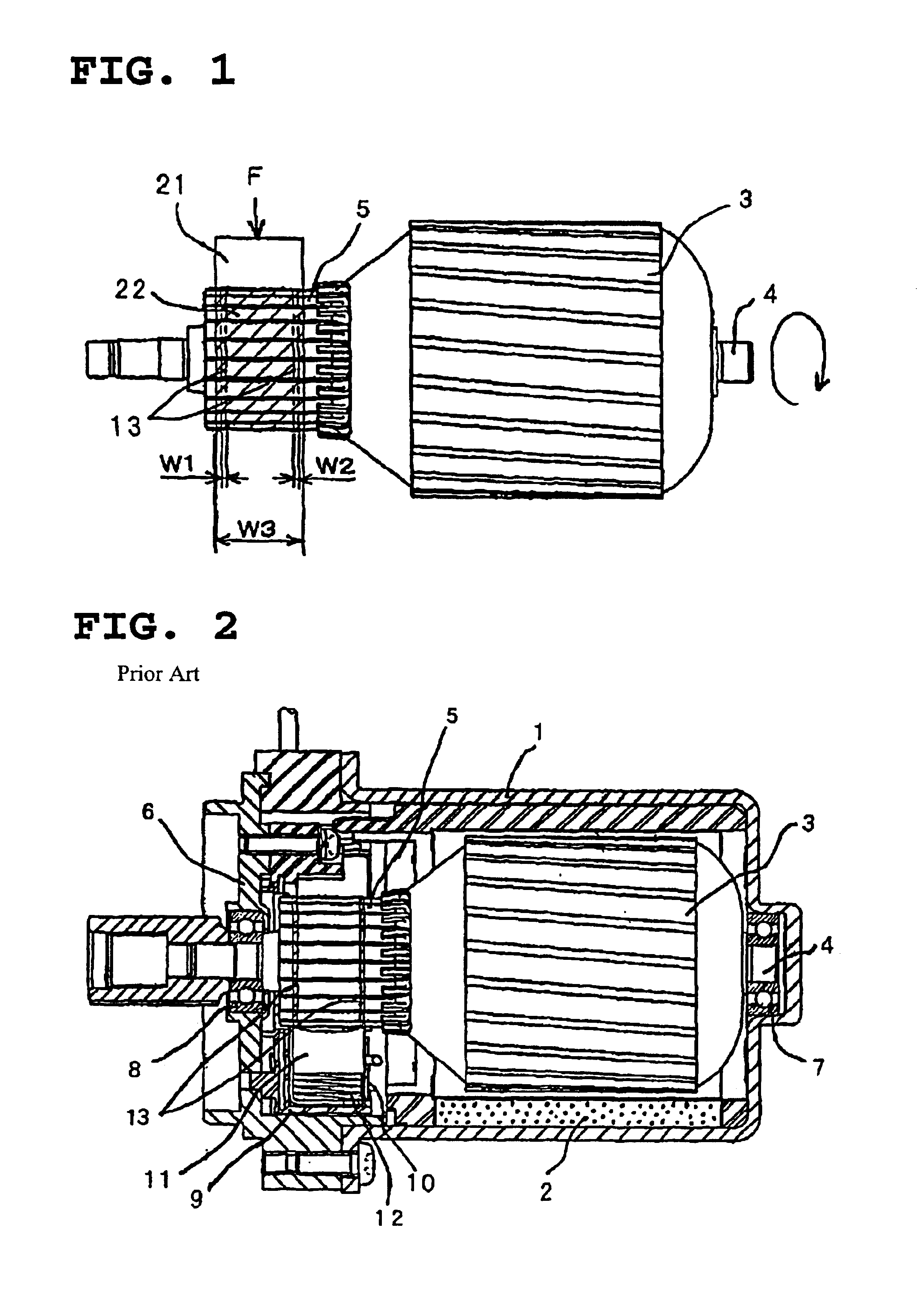
[0024]FIG. 1 shows a shakedown brush in a rotary electric machine and explains an aging process according to Embodiment 1, wherein the same numerical references are used for portions the same as or similar to those in the conventional technique. In FIG. 1, numerical reference 21 designates a shakedown brush, wherein the number of the shakedown brush is one, and loads of carbon and copper of the shakedown brush are different from those of the brushes 11 to set hardness of the shakedown brush low. Numerical reference 22 designates a sliding trace with the shakedown brush 21, and the numerical reference W3 designates the width of the sliding trace. A shape of the shakedown brush 21 is different from those of the brushes 11, wherein the width of the shakedown brush 21 is completely in contact with and slides on the commutator as shown in FIG. 1. The sliding trace 13 shown in FIG. 1 is marked for the purpose of comparing with a pair of sliding traces 13 with the brushes illustrated in FI...
embodiment 2
[0038]Although, in FIG. 1, the example that the armature stands as the single unit has been described. However, the surface of the commutator 5 may be rubbed with the shakedown brush 21 other than the brushes 11 in advance after assembling the armature 3, the bracket 6, and the bearing 8, and rotating these by an external means. In this case, the carbon coat is produced by the shakedown brush 21 in advance, and a burr or the like on the surface of the commutator 5 is removed in advance, whereby noise of the rotary electric machine is reduced in early stages, and the performance is stabilized, whereby the aging process can be reduced or abolished, the productivity can be improved, and the cost of the rotary electric machine can be lowered.
embodiment 3
[0039]In Embodiments 1 and 2, the number of shakedown brush 21 is one. However, the number may be two or more. In this case, the duration of the aging process can be efficiently reduced.
[0040]Needless to say that, in Embodiments 1, 2, and 3, the electric motor has been exemplified, effects similar thereto can be demonstrated in a generator.
[0041]The first advantage of the rotary electric machine according to the present invention is that the aging process can be reduced or oreliminated, the productivity can be improved, and the cost of the rotary electric machine can be lowered.
[0042]The second advantage of the rotary electric machine according to the present invention is that variations of noise and the performance can be reduced.
[0043]The third advantage of the rotary electric machine according to the present invention is that a motor for an electromotive power steering device having a stable performance and generating a low noise suitable for a mass production is obtainable at a ...
PUM
 Abstract
Description
Claims
Application Information
 - R&D
- Intellectual Property
- Life Sciences
- Materials
- Tech Scout
- Unparalleled Data Quality
- Higher Quality Content
- 60% Fewer Hallucinations
Browse by: Latest US Patents, China's latest patents, Technical Efficacy Thesaurus, Application Domain, Technology Topic, Popular Technical Reports.
© 2025 PatSnap. All rights reserved.Legal|Privacy policy|Modern Slavery Act Transparency Statement|Sitemap|About US| Contact US: help@patsnap.com


