Method and apparatus for cooling heat-generating structure

a heat-generating structure and apparatus technology, applied in lighting and heating apparatus, indirect heat exchangers, semiconductor/solid-state device details, etc., can solve the problems of large heat generation, large power consumption, heavy weight, etc., and achieve the effect of efficient cooling of heat-generating structures

a heat-generating structure and apparatus technology, applied in lighting and heating apparatus, indirect heat exchangers, semiconductor/solid-state device details, etc., can solve the problems of large heat generation, large power consumption, heavy weight, etc., and achieve the effect of efficient cooling of heat-generating structures

US6952345B2Inactive Publication Date: 2005-10-04RAYTHEON CO

Image

  • Method and apparatus for cooling heat-generating structure
  • Method and apparatus for cooling heat-generating structure
  • Method and apparatus for cooling heat-generating structure

Examples


Embodiment Construction

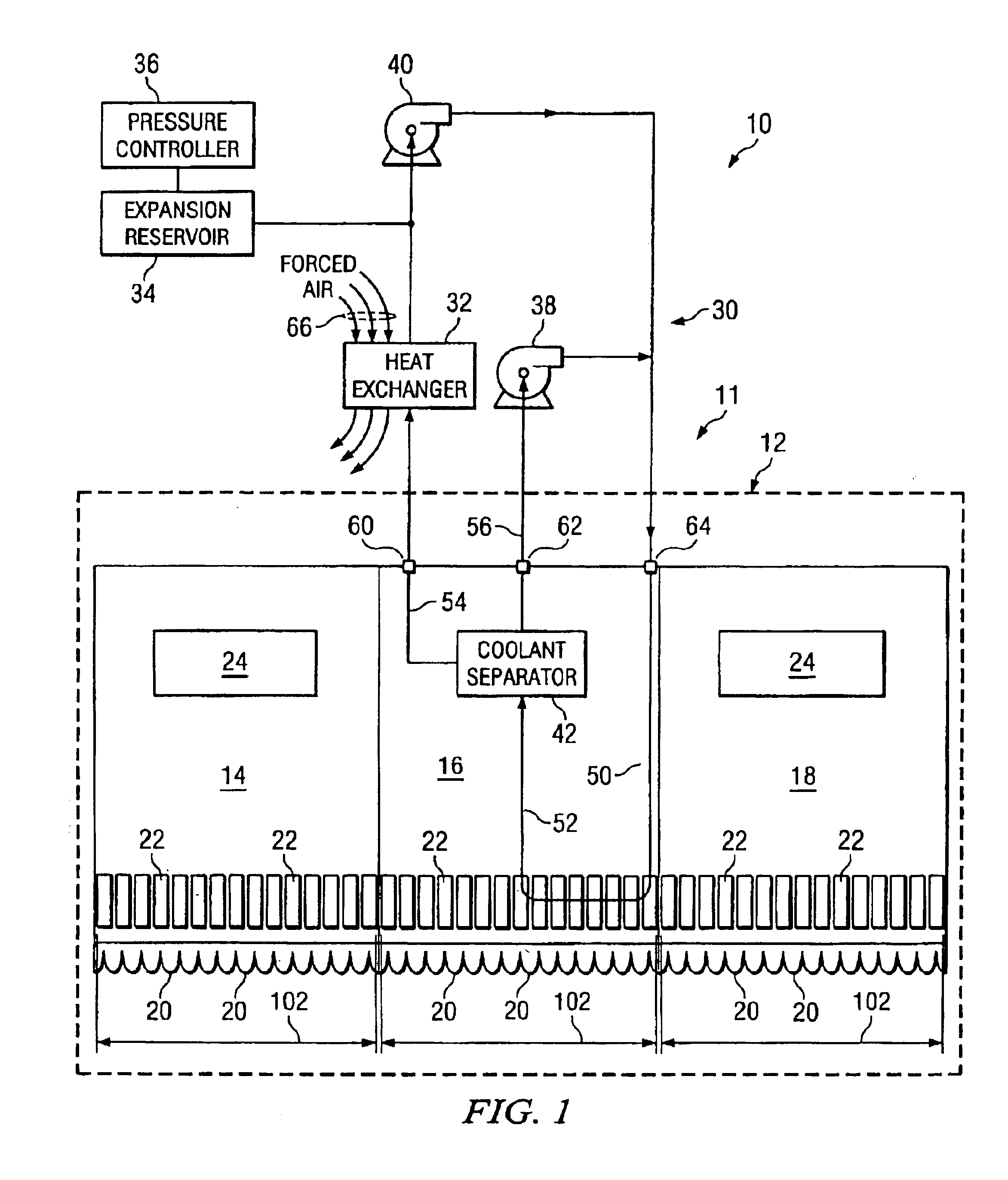
[0017]FIG. 1 is a block diagram of an apparatus 10 which includes part of a phased array antenna system 12, and a cooling system 11 for the phased array antenna system 12. The antenna system 12 includes a plurality of identical modular parts that are commonly known as slats, three of which are depicted at 14, 16 and 18. The cooling system 11 is configured to cool one or more slats, so as to remove heat generated by electronic circuitry thereon. For clarity, FIG. 1 shows how the cooling system 11 is configured to cool the slat 16, but the cooling system 11 also cools other slats in a similar manner, including the slats 14 and 18.

[0018]The antenna system 12 includes a two-dimensional array of antenna elements 20, each row of the array of antenna elements 20 being provided on one or more slats. For example, in the embodiment shown in FIG. 1, one row of antenna elements 20 is provided on the slats 14, 16 and 18. The slats 14, 16 and 18 abut each other edge-to-edge to form a continuous r...


PUM


Abstract

An apparatus includes a heat receiving portion which receives heat within a footprint from a heat generating structure, and a cooling arrangement which causes flow of a coolant that absorbs heat at the heat receiving portion, the cooling arrangement being disposed in its entirety within a width of the footprint in a particular direction. A different feature involves an apparatus which includes a heat receiving portion at which a coolant receives heat, and a coolant separating portion which receives coolant traveling away from the heat receiving portion, and which separates liquid coolant from vapor coolant.

Description

TECHNICAL FIELD OF THE INVENTION[0001]This invention relates in general to cooling techniques and, more particularly, to a method and apparatus for cooling devices which generate a substantial amount of heat.BACKGROUND OF THE INVENTION[0002]Some types of electronic circuits use relatively little power, and produce little heat. Circuits of this type can usually be cooled satisfactorily through a passive approach, such as convection cooling. In contrast, there are other circuits which consume large amounts of power, and produce large amounts of heat. One example is the circuitry used in a phased array antenna system.[0003]More specifically, a modern phased array antenna system can easily produce 25 to 30 kilowatts of heat, or even more. One known approach for cooling this circuitry is to incorporate a refrigeration unit into the antenna system. However, suitable refrigeration units are large, heavy, and consume many kilowatts of power in order to provide adequate cooling. For example,...

Claims


Application Information

Patent Timeline
04 Oct 2005
Publication
US6952345B2
IPC
F25B23/00; F28D15/02; H01L23/34; H01L23/427; H01Q1/02; H05K7/20
CPC
F28D15/0266; H01L23/427; H01Q1/02; H05K7/20272; H01L2924/0002; H01L2924/00
Inventors
WEBER, RICHARD M.; BARSON, GEORGE F.