
High performance transmission link and interconnect

a transmission link and high-performance technology, applied in the field of data communication networks, can solve the problems of insufficient reliability of the interconnection link in most data networks, inability to inability to provide hardware or software solutions that meet the requirements of complete, error-free, fast and in-order data transmission, etc., to improve the performance of the system, increase the bandwidth of the serial link, and improve the processing speed of the pack

Inactive Publication Date: 2005-10-04
ORACLE INT CORP
View PDF22 Cites 50 Cited by
  • Summary
  • Abstract
  • Description
  • Claims
  • Application Information

AI Technical Summary

Benefits of technology

[0009]The present invention describes methods and components in an interconnect system for improving the performance of the system with respect to increasing bandwidth in a serial link, increasing the processing speed of a packet in a node, and improving the calibration of links in the system. In one aspect of the present invention, a method of encoding framing data in a packet is described. A packet is a data unit having a specific number of flits, a flit, in turn, having a specific number of bits. For example, a flit, the data unit sent over a serial link in one clock cycle, can be 88 bits in length, and a packet can be made up of one, two, or four flits. If the packet is one flit, two framing bits are inserted into the packet. If the packet is two flits, four framing bits are inserted into the packet, and if it is a four-flit packet, eight framing bits are inserted. In this way, space in the packet for data is maximized and the total number of bits of the packet can be determined either after reading a first framing bit if the packet is one flit or after reading a second framing bit if the packet is two or four flits long.
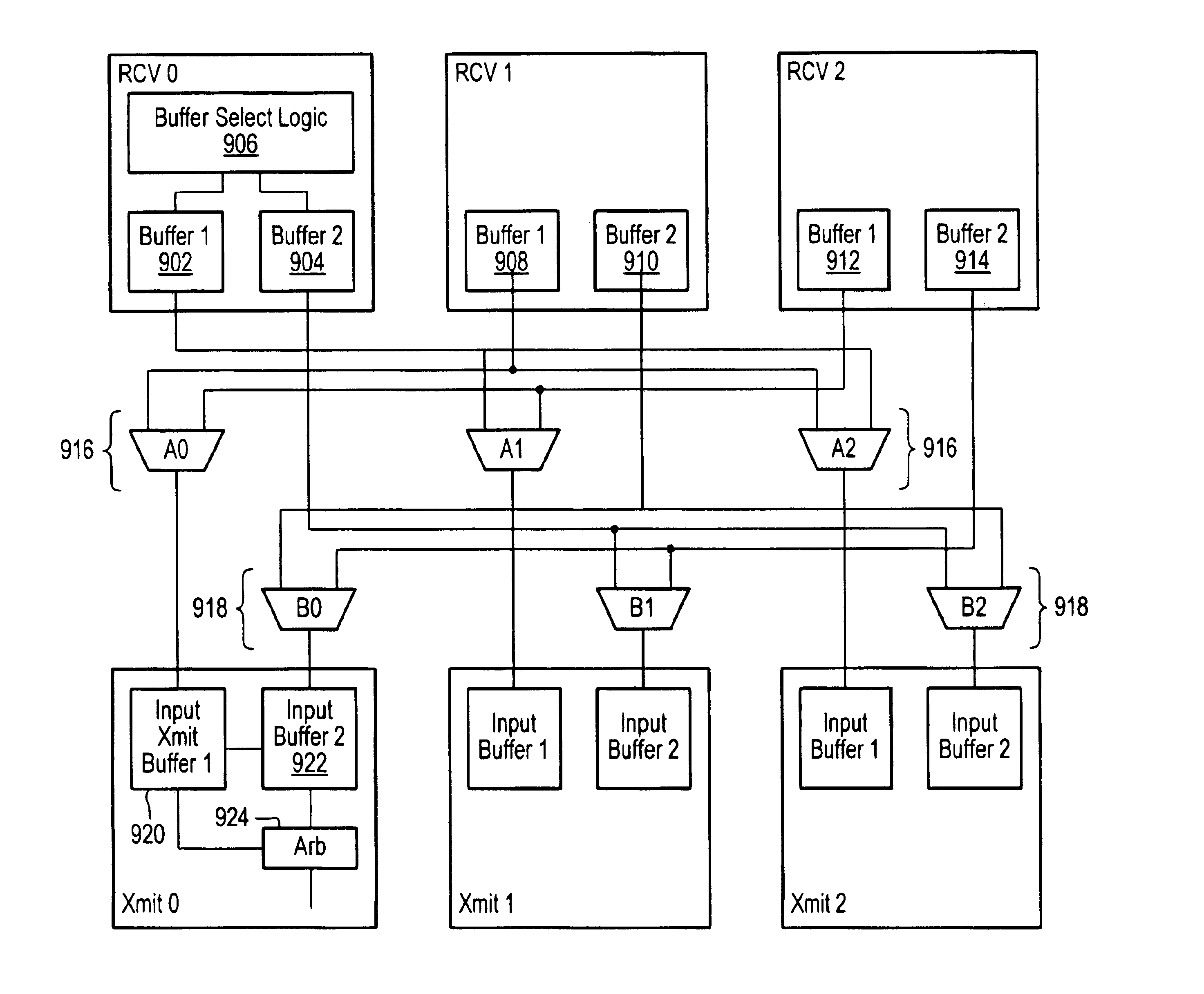
[0012]In another aspect of the present invention, a node in an interconnect system is described. A receiver in the node has two buffers. When the receiver gets a data segment, such as 8 bits of a flit, it examines a particular bit and determines, based on the bit, whether the data segment should go to a first buffer or a second buffer. For example, if the bit is a one, it will go to the first buffer and if it is a zero it will go to the second buffer. The node also has a dual crossbar, one for each buffer. A first crossbar receiving data segments from one buffer and the second crossbar receives data segments from the other buffer. This allows the potential routing of two data segments in one clock cycle to their respective transmitters so that one segment does not have to wait for the other segment to be routed.

Problems solved by technology

Presently, the interconnect links in most data networks are not sufficiently reliable to ensure that data reach destinations without errors and in proper order, and that failover actions be transparent to other nodes and users.
These software solutions fall short of the requirements for complete, error-free, fast, and in-order data transmission.
Presently, there are no hardware or software solutions that meet these requirements.
For example, with respect to coding and framing of data packets, both of which can consume significant bandwidth in a link.
If the transmitter waits longer than it needs to before re-sending the packet because the packet is lost, and bandwidth is being wasted.

Method used


Image

  • High performance transmission link and interconnect
  • High performance transmission link and interconnect
  • High performance transmission link and interconnect

Examples


Embodiment Construction

[0028]Reference will now be made in detail to a preferred embodiment of the invention. An example of the preferred embodiment is illustrated in the accompanying drawings. While the invention will be described in conjunction with a preferred embodiment, it will be understood that it is not intended to limit the invention to one preferred embodiment. To the contrary, it is intended to cover alternatives, modifications, and equivalents as may be included within the spirit and scope of the invention as defined by the appended claims.

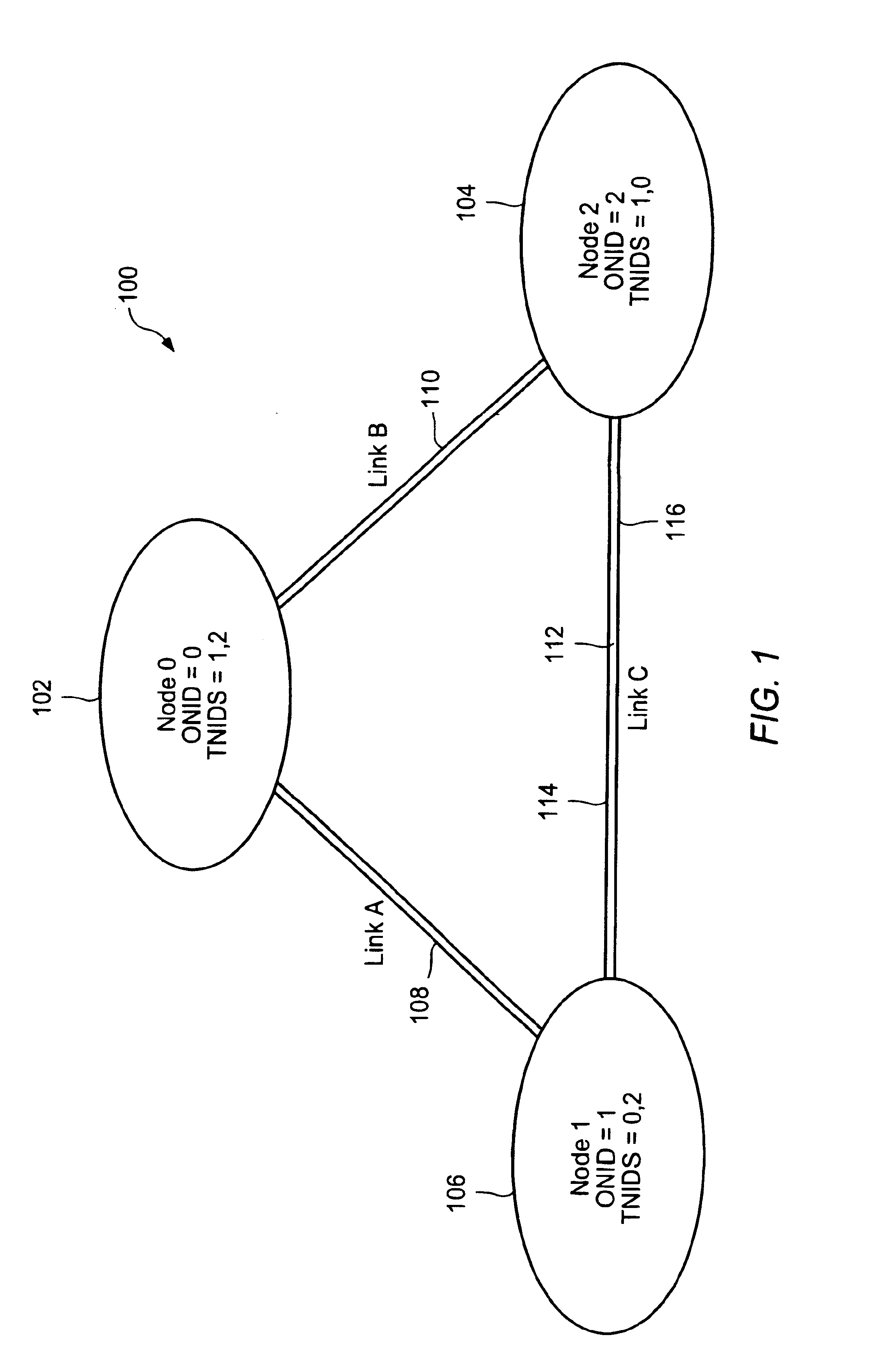
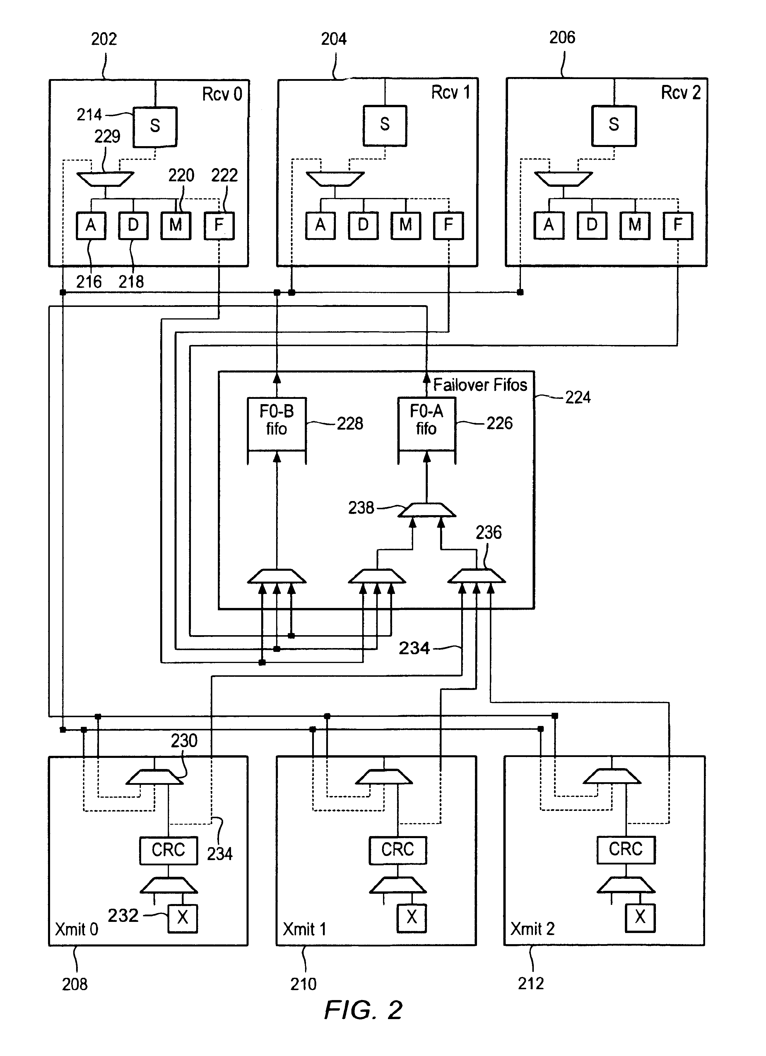
[0029]A system and method for optimizing the performance of an interconnect system is described in the various figures. Also described is a system and method for automatic link failover in data networks are described in the various figures. Automatic link failover enables data packet traffic scheduled to go over a particular link to be dynamically re-routed to an alternative path if the particular link should fail. Automatic link failover of the present inve...


PUM


Abstract

Methods and components in an interconnect system for improving the performance of the system with respect to increasing bandwidth in a serial link, increasing the processing speed of a packet in a node, and improving the calibration of links in the system are described. In one aspect of the present invention, a method of encoding framing data in a packet such that less than the normal number of framing bits is required. For example, a flit, the data unit sent over a serial link in one clock cycle, can be 88 bits in length, and a packet can be made up of one, two, or four flits. If the packet is a one- flit packet, two framing bits are inserted into the packet. If the packet is two flits, four framing bits are inserted into the packet, and if it is a four-flit packet, eight framing bits are inserted. In this way, space in the packet for data is maximized and the total number of bits of the packet can be determined either after reading a first framing bit if the packet is one flit or after reading a second framing bit if the packet is two or four flits long.

Description

CROSS-REFERENCE TO RELATED APPLICATIONS[0001]The present application is related to U.S. patent application Ser. No. 09 / 697,663, filed on Oct. 25, 2000, entitled, “AUTOMATIC LINK FAILOVER IN DATA NETWORKS”, which is incorporated herein by reference.BACKGROUND OF THE INVENTION[0002]1. Field of The Invention[0003]The present invention relates generally to data communication networks and the transmission of data in those networks and the transmission of data in the networks. More specifically, it relates to hardware and data encoding modifications for increasing the throughput and and error discrimination properties of data networks and decreasing the latency of data networks.[0004]2. Discussion of Related Art[0005]As the use of data communication networks becomes increasingly widespread, the need for reliable data transmission through nodes in such networks, the Internet being one example, has become more important. In addition, the standards for what is acceptable data transmission an...

Claims


Application Information

Patent Timeline
Patent Type & Authority Patents(United States)
IPC IPC(8): H04L12/56
CPCH04L45/22H04L45/28H04L49/557H04L49/552
Inventor CASSIDAY, DANIEL R.SATTERFIELD, DAVID L.
Owner ORACLE INT CORP
Learn More