Method for scroll-free machining rotationally symmetrical surfaces

a technology of rotationally symmetrical surfaces and cutting machining, which is applied in the direction of turning machines, turning machines accessories, turning apparatuses, etc., can solve the problems relatively slow machining advance or and the effect of low level of machining outpu

Inactive Publication Date: 2005-10-11
BOEHRINGER WERKZEUGMASCHEN
View PDF9 Cites 9 Cited by
  • Summary
  • Abstract
  • Description
  • Claims
  • Application Information

AI Technical Summary

Benefits of technology

[0023]Therefore the object in accordance with the invention is to provide a process for machining rotating rotationally symmetrical workpieces with a defined cutting edge, in which the resulting rotationally symmetrical su...

Problems solved by technology

Machining after the hardening operation is generally necessary, even if the preliminary machining operation is effected with a high degree of precision, as, after the hardening process, in part considerable degrees of distortion due to hardening generally occur.
As the cutting machining data, particularly when dealing with hardened workpieces, for high levels of surface quality, are generally very small, this frequently involves a relatively slow machining advance or a low level of machining output.
While the relatively low level of machining output involves a marked economic disadvantage, the twist-bearing surfaces give rise to problems in relation to seals which bear thereagainst, particularly if they are moving relative to the surface, for example a rotating shaft within a stationary seal.
Particularly in the case of machines which for example for reasons of hygiene or also for reasons of environmental protection, must run without leakage, this represents a problem which is to be taken seriously.
In addition, the sealing elements which bear against the surface with the twist configuration thereon suffer a great deal of damage with time at the contact lines or surfaces therebetween, due to those thread-shaped grooves or raised portions, or they are at least subjected to a severe abrasive effect.
If however the plunge-cut cutting edge is as wide in the axial direction as the rotationally symmetrical surface which is to be produced overall, very high cutting forces occur, particularly whe...

Method used


Image

  • Method for scroll-free machining rotationally symmetrical surfaces
  • Method for scroll-free machining rotationally symmetrical surfaces
  • Method for scroll-free machining rotationally symmetrical surfaces

Examples


Embodiment Construction

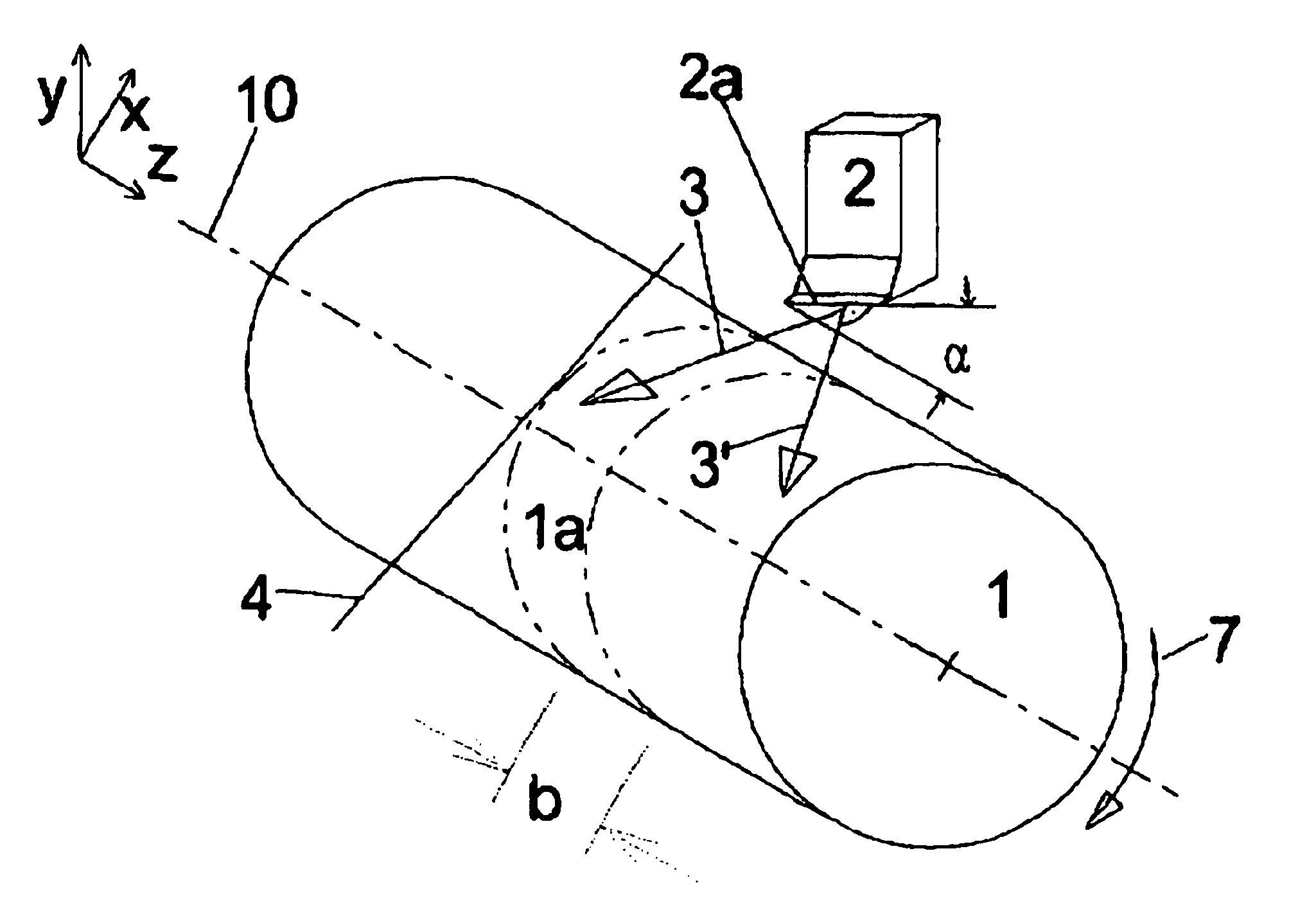
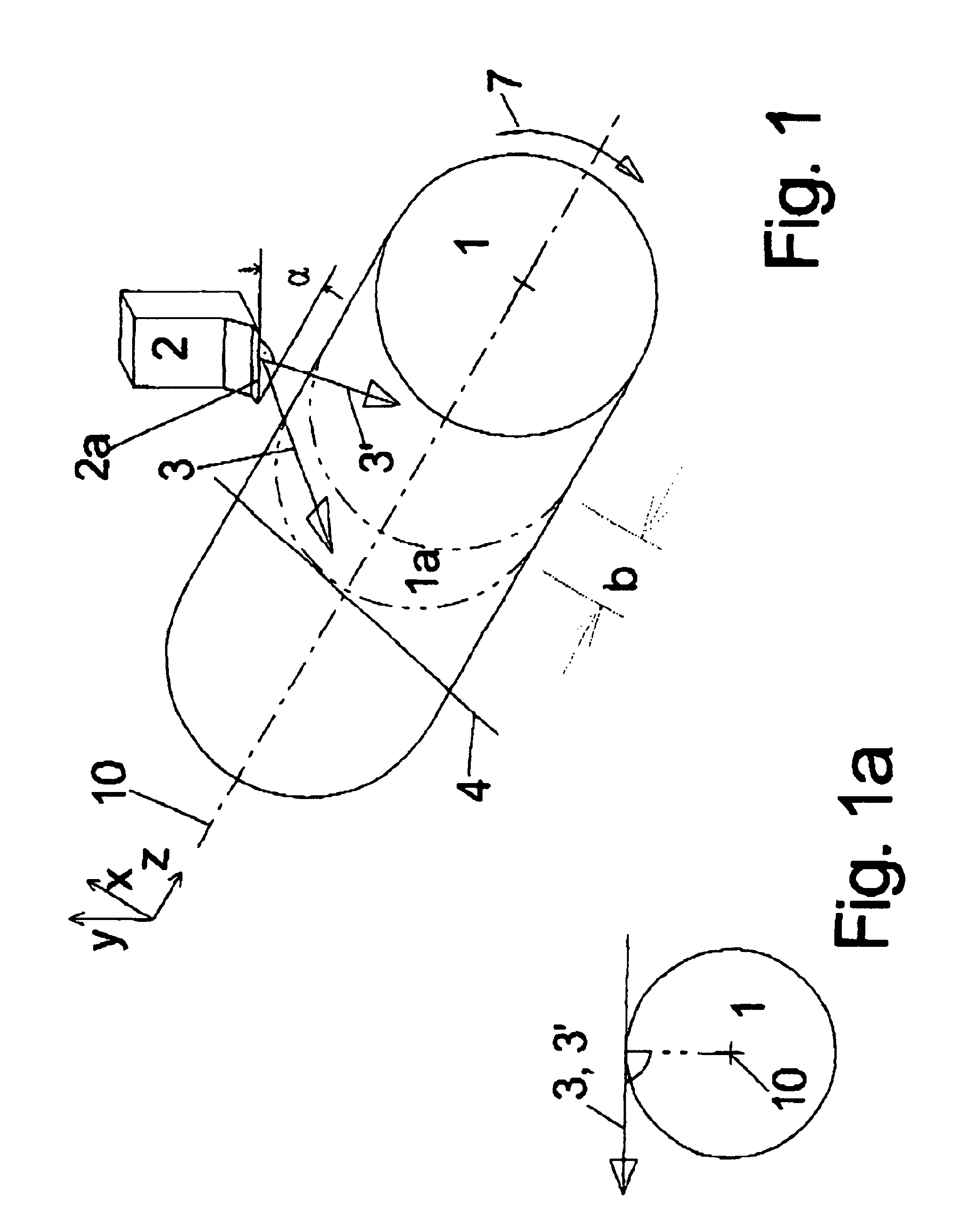
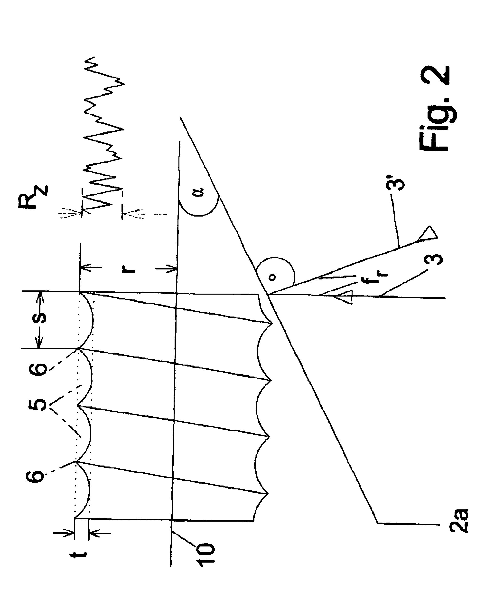
[0033]With a uniform advance feed f, expressed in mm / revolution of the workpiece, the result is a helical groove 5, the pitch spacing of which in the direction of the axis of rotation 10 is constant, with a uniform feed f. In this respect, it will be seen that the depth t′ of those grooves depends on the size of the corner radius rE of the cutting tool producing the shape: the greater that corner rE is, the correspondingly shallower are the flanks of the groove and thus the depth t′ becomes correspondingly less. The relationship in terms of a formula reads as follows: t=f28·rE

[0034]In this respect, setting at least one of the edges of the cutter, in particular the secondary cutter, which lead to the cutter corner, at the smallest possible angle, preferably parallel, with respect to the direction of the axis of rotation 10, generally involves the only viable option for minimising the depth t′ as, by virtue of predetermined cycle times etc in production the feed f cannot be reduced ju...


PUM

PropertyMeasurementUnit
Angleaaaaaaaaaa
Angleaaaaaaaaaa
Angleaaaaaaaaaa

Abstract

A process for cutting machining of rotating rotationally symmetrical workpieces with a defined cutting edge, wherein the resulting rotationally symmetrical surface has either no twist or a twist which is only insignificant in terms of transport effect and abrasive action and/or when machining the hardened workpiece surfaces a particularly high material removal rate can be achieved, wherein a cutting edge which is askew with respect to the axis of rotation of the workpiece is guided in contacting relationship along the rotating workpiece in a linear feed movement transversely with respect to the axis of rotation, wherein the machining parameters, in particular the broaching feed and the inclined positioning of the cutting edge are so selected that the twist occurring at the machined surface becomes a minimum in respect of twist pitch and/or twist depth and in particular the twist depth becomes a minimum.

Description

CROSS-REFERENCE TO RELATED APPLICATION[0001]This is an United States National Phase Application entitled “Process for Twist-Free Cutting Machining of Rotationally Symmetrical Surfaces” claiming priority to PCT Application No. PCT / EP00 / 12913 having an International Filing Date of 18 Dec. 2000, which claims priority to German Application Nos. 19961111.4 filed 17 Dec. 1999 and 19963897.7 filed 30 Dec. 1999.BACKGROUND OF INVENTION[0002]The invention concerns the cutting machining of rotating, in particular concentric rotationally symmetrical surfaces of a metal workpiece, in particular of steel or cast iron, even in the hardened state, by means of a geometrically defined cutting edge or cutting edges.[0003]The rotary machining of rotationally symmetrical parts both in the soft and also in the hardened state with a geometrically defined cutting edge is state of the art. The processes involving grinding, finishing, honing and similar processes are in part substituted in that respect.[0004...

Claims


Application Information

Patent Timeline
IPC IPC(8): B23B1/00
CPCB23B1/00Y10T82/16016Y10T82/10
Inventor SCHREIBER, LEOTROTT, KLAUS
Owner BOEHRINGER WERKZEUGMASCHEN
Why Eureka
Try Eureka