Multilayer molded element

a multi-layer, molded element technology, applied in the direction of superstructures, sound producing devices, vehicular safety arrangments, etc., can solve the problems that the hollow spaces that are accessible to water and mud cannot be developed, and achieve the effect of low weight, efficient noise reduction, and large elastic volum

Inactive Publication Date: 2005-10-11
JOHANN BORGERS
View PDF26 Cites 25 Cited by
  • Summary
  • Abstract
  • Description
  • Claims
  • Application Information

AI Technical Summary

Benefits of technology

[0007]The basic benefit of the multi-layer construction according to the invention includes that the kinetic energy of impinging projectiles (stones, water droplets etc.) is distributed and attenuated over a large elastic volume. The entire element achieves efficient noise reduction, while low in weight, and this applies both with respect to excitation from projectiles as well as with respect to rolling motion noise. Whereas with relatively hard shells, the exterior noise is reflected and again radiated, with the molded element according to the invention it is possible substantially deposit the sound energy in the elastic-mass-system, which is formed by the relatively thick elastic and the wheel-side cover layer or cover lays, so that it is dissipated therein. In ad

Problems solved by technology

This results in complete sealing of the inner elastic layer, so th

Method used


Image

  • Multilayer molded element
  • Multilayer molded element
  • Multilayer molded element

Examples


Embodiment Construction

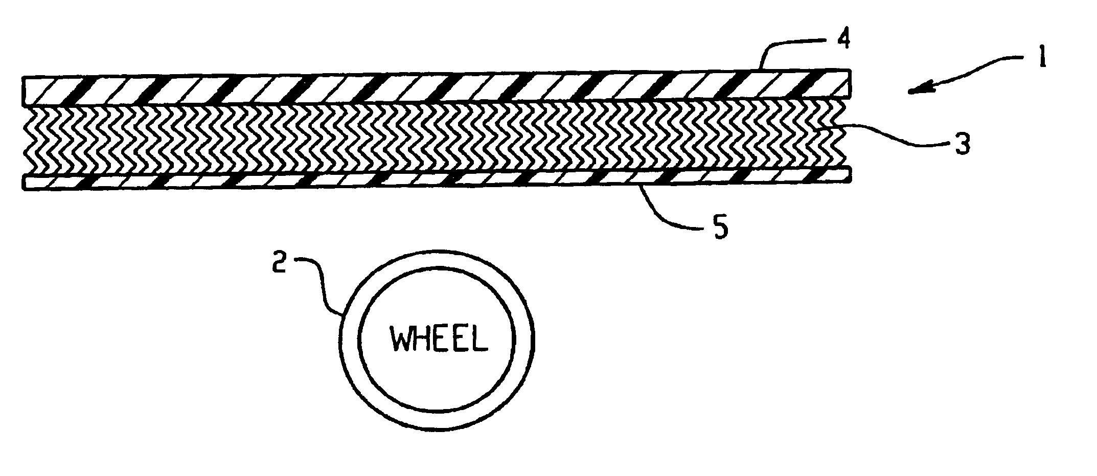
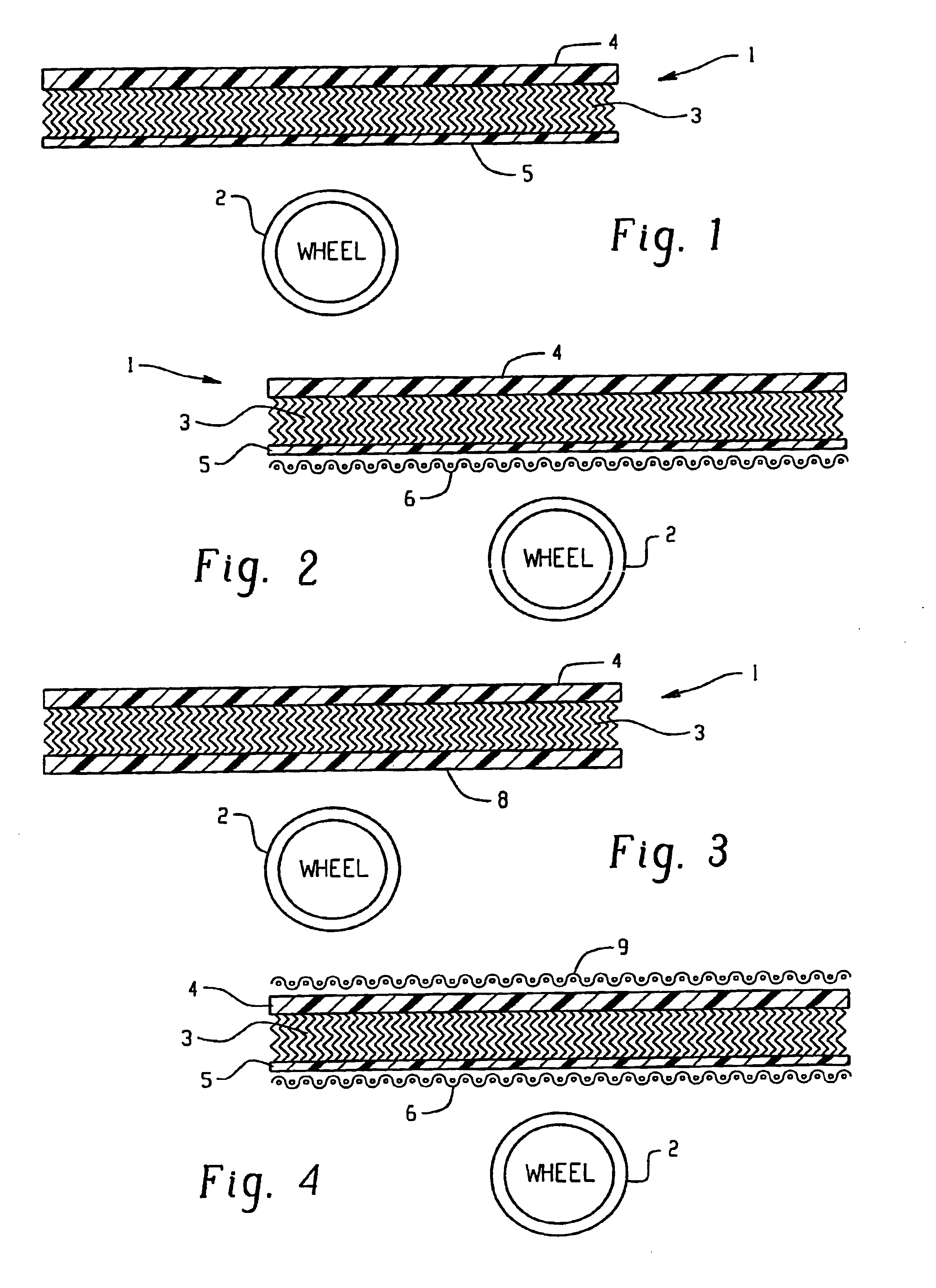
[0024]FIGS. 1 to 4 present variations of the layered construction of a molded or structural element 1 according to the invention. For identification of position, a wheel 2 is respectively indicated.

[0025]In FIGS. 1 to 4, the relatively thick elastic layer, enclosed by cover layers 4, 5 (and / or 8 ) is designated with 3. Layer 4, respectively located on the side facing the vehicle, is a sufficiently heavy (approximately 500 μm) thermoplastic or duroplastic cover layer (made for example of polypropylene film or resin-coated PES fabric) which contributes not only the sealing function but also mechanical stability to the structural element 1 and which serves as a base for the assembly.

[0026]In the embodiment according to FIG. 1, Layer 5 is provided on the wheel side. This involves, for example, a film made of thermo- or duro-plastic material, whose essential function it is to absorb and distribute the impact energy. This film is so thin (e.g. 1000 μm) that solid-borne sound excitation do...


PUM


Abstract

A multilayer molded element (1) is molded to an appropriate shape which conforms to an underside of floor areas or wheel housings of a vehicle. The multilayer structure includes a non-woven, resilient layer (3) which functions as a shock absorber and spring to absorb impact and damp noise. The resilient layer is disposed between cover layers (4, 5). Optionally, fabric layers (6, 7) are bonded to outsides of the cover layers.

Description

BACKGROUND OF THE INVENTION[0001]The invention relates to a multilayer molded element suitable for bottom covering of vehicle floor areas or wheel housings. Molded elements of this type are utilized in order to protect the automobile body from whirled-up stones as well as spray water and in order to diminish the noise level in the interior of the vehicle and on the outside the vehicle.[0002]When driving on gravel-paved streets and on wet roadways, stones and / or droplets of water are carried along by the tires and propelled at high speed against the vehicle body. On the one hand, this causes damage to the vehicle finish on the underside, so that corrosion may set in. In addition, the transfer of energy from the stones to the vehicle body leads to a broad-band, impulse-like vibration excitation (sound conducted through solids) of the vehicle body, which is radiated into the interior of the vehicle or outside of same in form of rattling—or crackling noise.[0003]Hitherto customary facin...

Claims


Application Information

Patent Timeline
IPC IPC(8): B62D25/16B62D25/18B60R13/08G10K11/00G10K11/168G10K11/162
CPCB60R13/0861B62D25/161B62D25/18G10K11/162G10K11/168B32B2307/102
Inventor FRIEST, CHRISTOPHEICHHORN, GEORGSEIFERT, MEINOLFDOPHEIDE, RALF
Owner JOHANN BORGERS
Why Eureka
Try Eureka