Acceleration sensor

a sensor and acceleration technology, applied in the field of acceleration sensors, can solve the problems of extremely reduced contact between the movable electrode and the substrate, and achieve the effects of easy manufacturing of acceleration sensors, reduced mass of the movable portion, and easy destruction

Inactive Publication Date: 2005-10-18
MITSUBISHI ELECTRIC CORP
View PDF8 Cites 68 Cited by
  • Summary
  • Abstract
  • Description
  • Claims
  • Application Information

AI Technical Summary

Benefits of technology

[0019]An acceleration sensor according to the invention includes a first and a second fixed electrodes provided on a substrate, a movable electrode which is provided above the first and second fixed electrodes by facing against them, and elastically and swingably supported on the substrate by a first elastic supporting body, a mass which is elastically supported on the substrate by a second elastic supporting body and is movable in response to an acceleration in a direction perpendicular to the substrate, and a linking portion for linking the movable electrode and the mass at a position away from a swing axis of the movable electrode by a predetermined distance. In this case, an acceleration is measured based on changes in a first capacitance by the first fixed electrode and the movable electrode and a second capacitance provided by the second fixed electrode and the movable electrode. Therefore, the displacement amount at the end of the movable electrode can be larger than the displacement amount of the mass when an acceleration is applied. In other words, a large detected capacity change can be obtained by a small displacement of the mass. Therefore, an acceleration sensor for detecting an acceleration with high sensitivity can be obtained without decreasing the rigidity of the torsion bar more than necessary. By improving the rigidity of the movable part, the sensitivity to the other axes is suppressed. Thus, a high impact resistant and highly reliable acceleration sensor can be obtained.
[0020]The movable electrode may be surrounded by the mass such that the center of gravity of the movable electrode and the center of gravity of the mass can coincide each other. Therefore, the balance of the movable electrode is maintained also at the initial state. Thus, the same initial capacity values of the capacitances can be obtained between the first fixed electrode and the movable electrode and between the second fixed electrode and the movable electrode. Therefore, the precision in measurement can be stabilized, and the calibration step can be easier.
[0022]A driving electrode is provided facing against the movable electrode on the substrate for driving a movable electrode to a predetermined position by applying a voltage between the driving electrode and the movable electrode. Thus, the acceleration sensor may be also of the servo type for returning a twist of a movable electrode caused in response to an applied acceleration to the original state by adjusting a voltage to be applied to the driving electrode. Therefore, the detection characteristic can be stabilized. Additionally, the possibility that the movable electrode and the substrate touch each other is extremely decreased. As a result, an highly reliable acceleration sensor can be obtained.
[0023]A correcting electrode is provided facing against the mass on the substrate for correcting a characteristic change due to a temperature change in an environment in use. Thus, an error in an acceleration obtained in the environment in use can be prevented.
[0026]At least the movable electrode, the mass, the first bar, the second bar and the third bar may be integrally formed by polysilicon. Thus, the acceleration sensor can be manufactured easily. Furthermore, as the mass of the movable portion can be reduced significantly, the sensor structure is hard to destroy even when an excessive acceleration is applied. Therefore, the impact resistance can be improved.
[0027]Furthermore, at least the movable electrode, the mass, the first bar, the second bar and the third bar may be integrally formed by monocrystal silicon. Thus, the acceleration sensor can be manufactured easily. Additionally, the thicknesses of the movable electrode and mass can be adjusted easily. The mass of the mass and / or the capacitance can be set arbitrarily. Accordingly, the flexibility in designing the acceleration sensor can be increased.

Problems solved by technology

Additionally, the possibility that the movable electrode and the substrate touch each other is extremely decreased.

Method used


Image

  • Acceleration sensor
  • Acceleration sensor
  • Acceleration sensor

Examples


embodiment 1

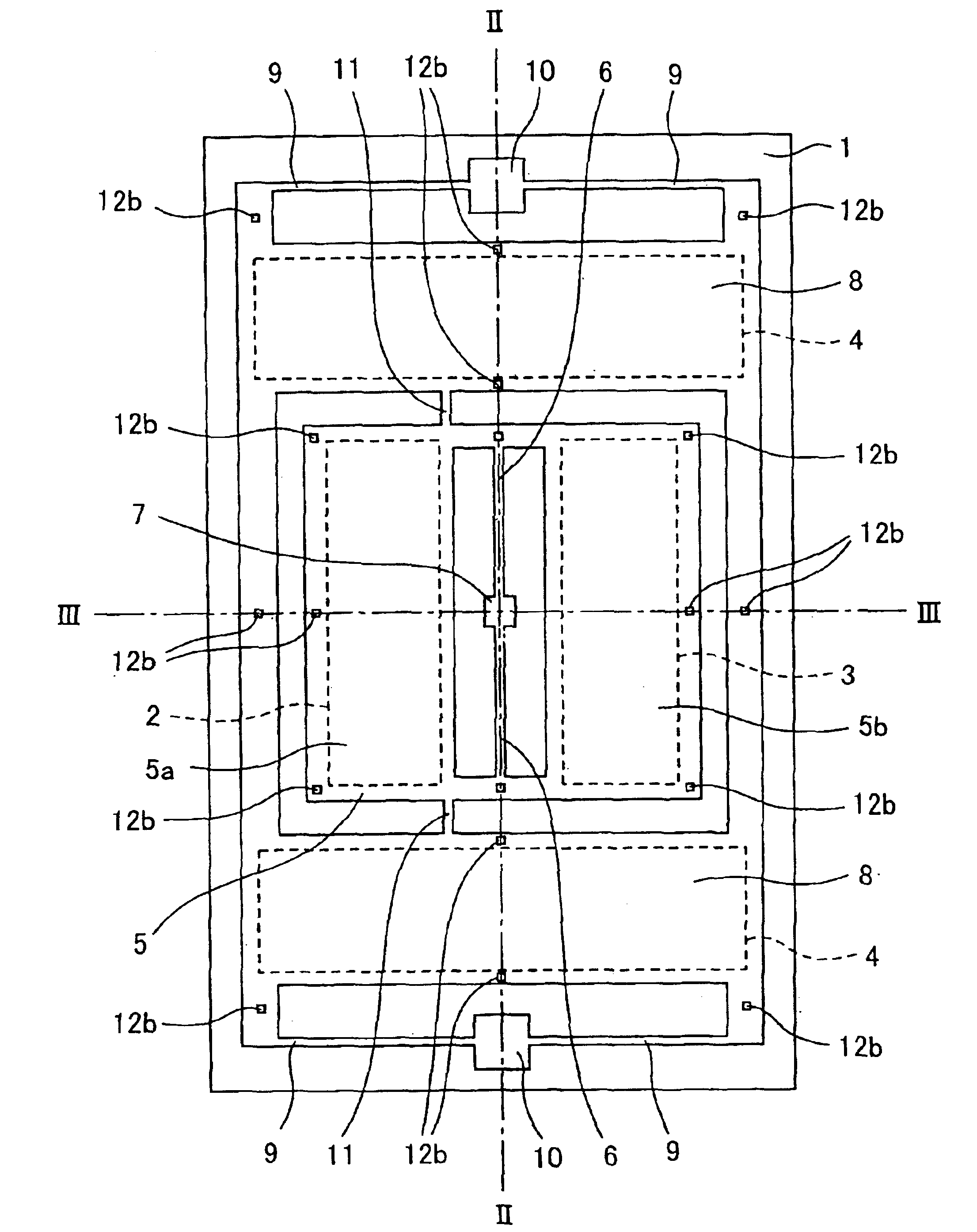
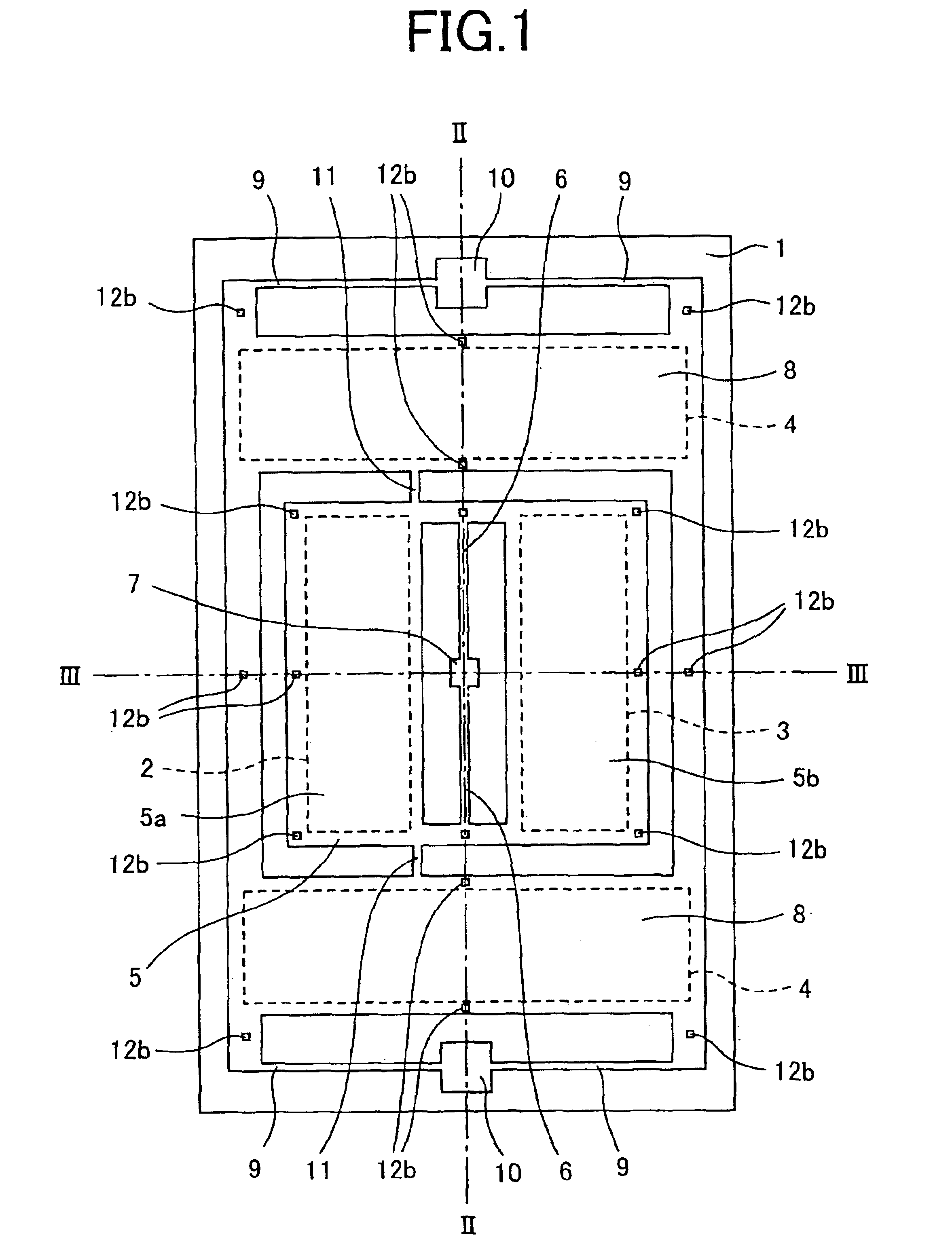
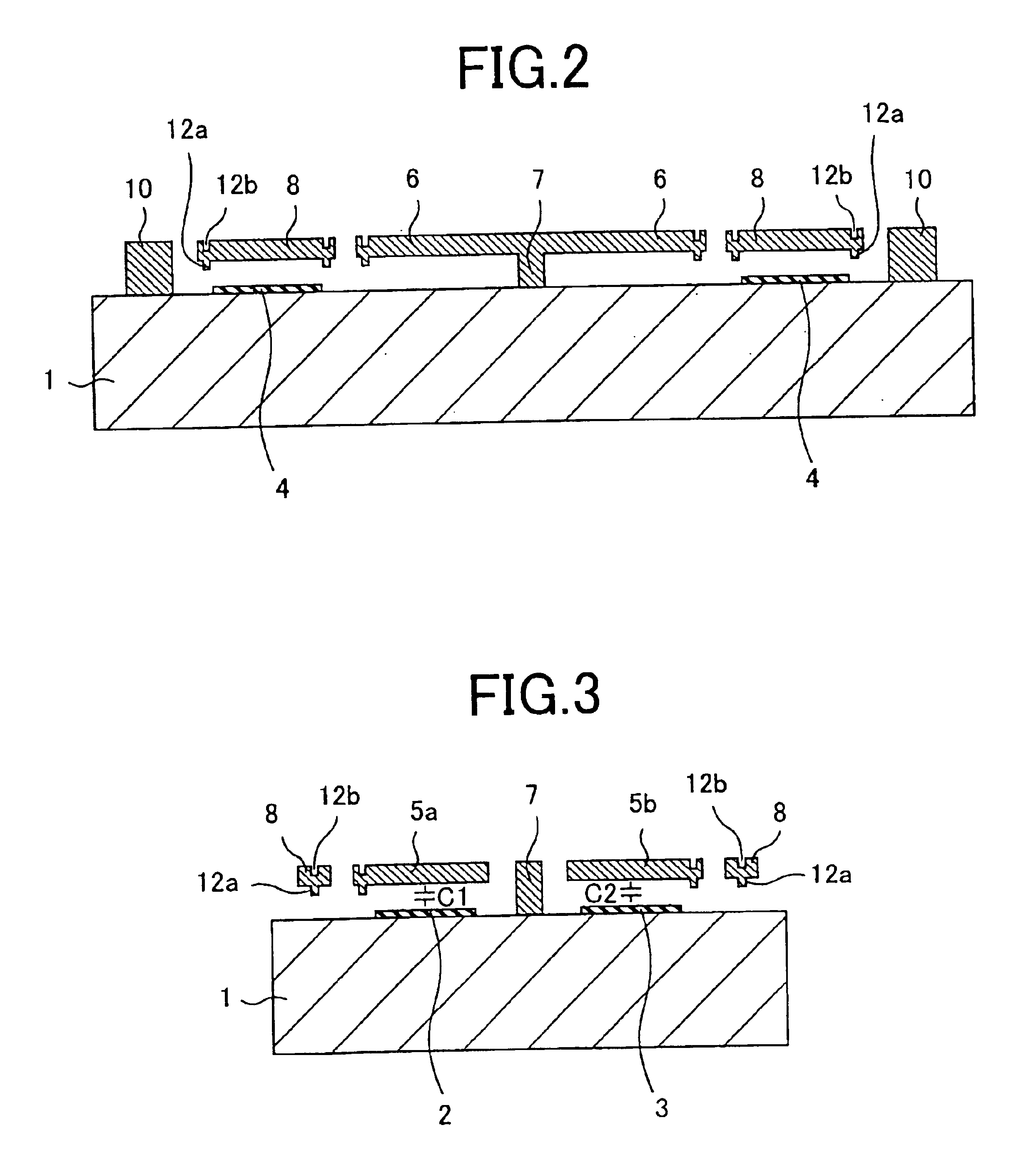
[0058]FIG. 1 is a plan view of an acceleration sensor according to Embodiment 1 of the invention. FIGS. 2 and 3 are sectional views taken along lines II—II and III—III, respectively, in FIG. 1. A construction of the acceleration sensor according to Embodiment 1 of the invention will be described with reference to these diagrams. A reference numeral 1 indicates a silicon substrate. An insulating film is preferably provided on the surface. The insulating film is not shown for a simple description. A low-stress silicon nitride film deposited by LPCVD is suitable for the insulating film. A first fixed electrode 2, a second fixed electrode 3 and a self-diagnosis electrode 4 are provided on the silicon substrate 1. The first fixed electrode 2, second fixed electrode 3 and self-diagnosis electrode 4 can be formed simultaneously by etching a polysilicon film deposited by LPCVD method, for example.

[0059]A reference numeral 5 is a movable electrode. The movable electrode 5 is placed above the...

embodiment 2

[0084]FIG. 8 is a plan view of an acceleration sensor according to Embodiment 2 of the invention. FIGS. 9 and 10 are sectional views taken along lines IX—IX and X—X, respectively, in FIG. 8.

[0085]Embodiment 2 is characterized in that a correcting electrode 32 is provided by the side of a self-diagnosis electrode 4 provided on a silicon substrate 1 by facing against a mass 8, in that driving electrodes 35 and 36 are provided near a first fixed electrode 2 and a second fixed electrode 3 provided on the silicon substrate 1 by facing against a movable electrode. 5, and in that a supporting bar 38 having a bending portion 37 is provided as a supporting bar for elastically supporting the mass 8 with respect to the silicon substrate 1 and the supporting bar 38 elastically supports the mass 8 with respect to the silicon substrate 1 through an anchor 39.

[0086]In FIGS. 8 to 10, the same reference numerals as those shown in FIGS. 1 to 7 indicate the same elements as those according to Embodime...

embodiment 3

[0094]FIG. 12 is a plan view of an acceleration sensor according to Embodiment 3 of the invention. FIGS. 13 and 14 are sectional diagrams taken along lines XIII—XIII and XIV—XIV, respectively, in FIG. 12.

[0095]In Embodiments 1 and 2, various electrodes are formed on the silicon substrate 1 by using a polysilicon film. Embodiment 3 is different from Embodiments 1 and 2 largely in that the various electrodes are formed of a metal thin film or monocrystal silicon on a glass substrate.

[0096]In FIGS. 12 to 14, a reference numeral 51 indicates a glass substrate. A first fixed electrode 52, a second fixed electrode 53, a self-diagnosis electrode 54, a correcting electrode 55 and driving electrodes 56 and 57 made of a metal thin film such as that of aluminum and gold are provided on the glass substrate 51. A movable electrode 58 is provided above the first fixed electrode 52, the second fixed electrode 53 and the driving electrodes 56 and 57 by being spaced from and facing against them. The...


PUM


Abstract

An acceleration sensor includes first and second fixed electrodes on a substrate, and a movable electrode located above the first and second fixed electrodes, with respect to the substrate, and facing them. The movable electrode is elastically supported on the substrate by a first elastic supporting body and is movable. A mass, which is elastically supported on the substrate by a second elastic supporting body, moves in response to an acceleration in a direction perpendicular to the substrate. A linking portion links the movable electrode and the mass at a position spaced from an axis of movement of the movable electrode by a distance. Acceleration is measured based on changes in a first capacitance between the first fixed electrode and the movable electrode and a second capacitance between the second fixed electrode and the movable electrode. Thus, a highly impact resistant and highly reliable acceleration sensor is obtained.

Description

[0001]This disclosure is a continuation-in-part of U.S. patent application Ser. No. 10 / 450,054, filed Jun. 10, 2003 now abandoned.TECHNICAL FIELD[0002]The present invention relates to an acceleration sensor and, in particular, to a highly reliable, high impact resistant acceleration sensor.BACKGROUND ART[0003]FIG. 16 is a plan view of a conventional acceleration sensor, which is disclosed in Japan Laid Open Hei5-133976, for example. FIG. 17 is a sectional view taken at a line XVII—XVII in FIG. 16.[0004]In FIGS. 16 and 17, a reference numeral 101 indicates a substrate. A first detecting electrode 102, a second detecting electrode 103 and a driving electrode 104 are provided on the substrate 101.[0005]A reference numeral 105 indicates a movable electrode. The movable electrode 105 is provided within a frame of a semiconductor material 106 by facing against the first detecting electrode 102, the second detecting electrode 103, and the driving electrode 104. The movable electrode 105 is...

Claims


Application Information

Patent Timeline
Patent Type & Authority Patents(United States)
IPC IPC(8): G01P15/125
CPCG01P15/125
Inventor YOSHIKAWA, EIJITSUGAI, MASAHIROKONNO, NOBUAKIHIRATA, YOSHIAKI
Owner MITSUBISHI ELECTRIC CORP
Why Eureka
Try Eureka