Storm drain movable baffle

a technology of storm drain and baffle, which is applied in the direction of water cleaning, liquid displacement, separation processes, etc., can solve the problems of difficult management, inability to easily modify the design of the system, and the short-term increase in the flow of municipal drainage systems, so as to prevent damage to the baffle and the mounting device, and prevent a large amount of unwanted debris. , the effect of economic efficiency

Inactive Publication Date: 2005-10-18
MUELLER INT LLC
View PDF14 Cites 18 Cited by
  • Summary
  • Abstract
  • Description
  • Claims
  • Application Information

AI Technical Summary

Benefits of technology

[0004]The present invention provides an economically efficient solution to this problem by providing a baffle that operates substantially in two positions in a drain passage and after shifting from a low flow position to a high flow position, the baffle will automatically return to the low flow position when the flow volume changes. In the low flow position, the baffle extends in a plane that is substantially perpendicular to the direction of flow through the drain passage and is maintained in this position by a torque limit mounting while, in the high flow position, the baffle moves under the action of the flow and is released at a preset load by the torque limit mounting to move out of the way of the flow. When the flow drops, the baffle will return to its original position, that is, vertically extending across the flow. In the low flow position, the baffle acts to impede floating waste material and debris from flowing to the treatment facility. The strength of the torque limit mounting will determine the magnitude of the load caused by an increased flow at which the baffle will pivot to move out of the flow path and allow the flow to pass such as to a diversion channel and out of the drainage system. This function will prevent damage to the baffle and baffle mounting device while preventing a large amount of unwanted debris from reaching the water treatment facility.

Problems solved by technology

However, the design of the system cannot be easily modified due to the size of the prefabricated portions and the necessity to establish safe flow conditions to prevent wastewater overflow and local flooding.
One particular difficulty in municipal drainage systems is accommodating short term increased flow due to storms of infrequent but large magnitude in terms of rainfall over a short interval.
These are particularly difficult to manage where solid waste material must be impeded that is often included in the flow through the system.
The problem becomes critical in storm events where the waste treatment facility is unable to handle the overflow and diversion of the flow is effected to prevent backup flooding.
A particular problem exists with respect to handling floating debris and waste material in such systems.

Method used


Image

  • Storm drain movable baffle
  • Storm drain movable baffle
  • Storm drain movable baffle

Examples


Embodiment Construction

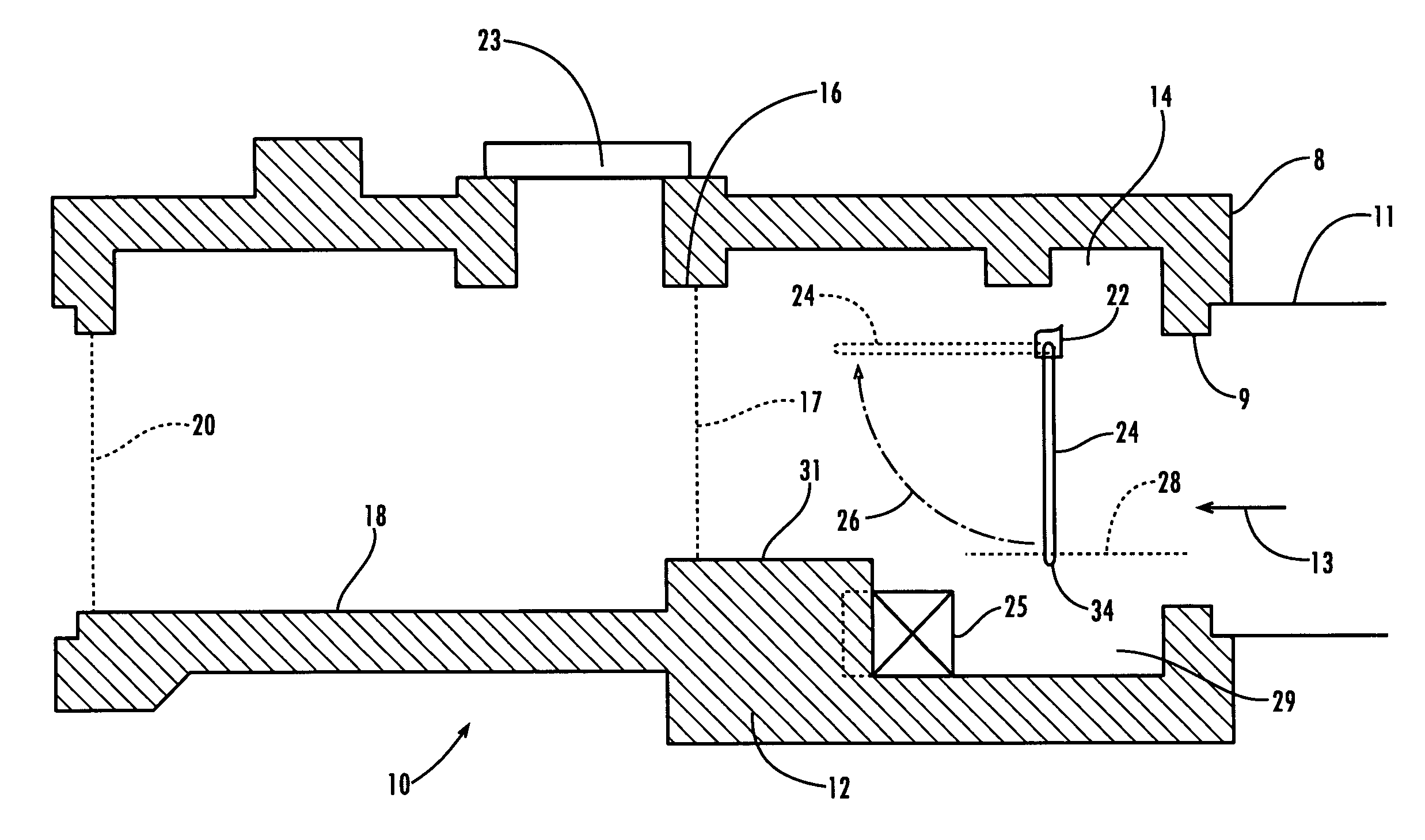
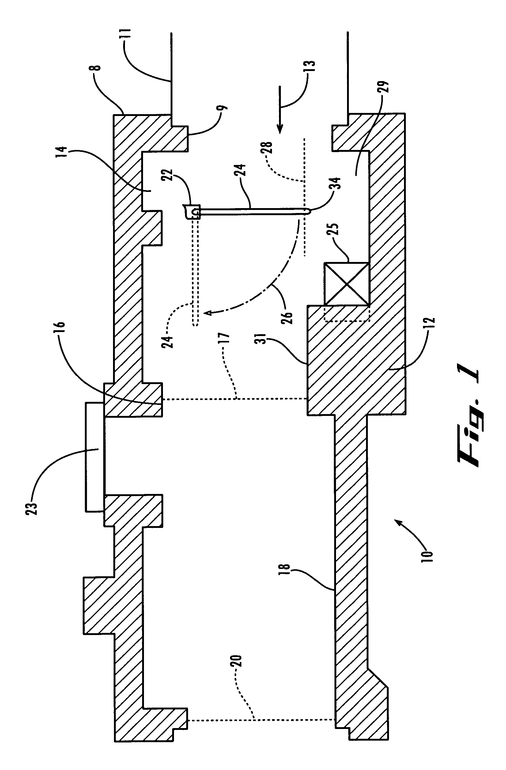
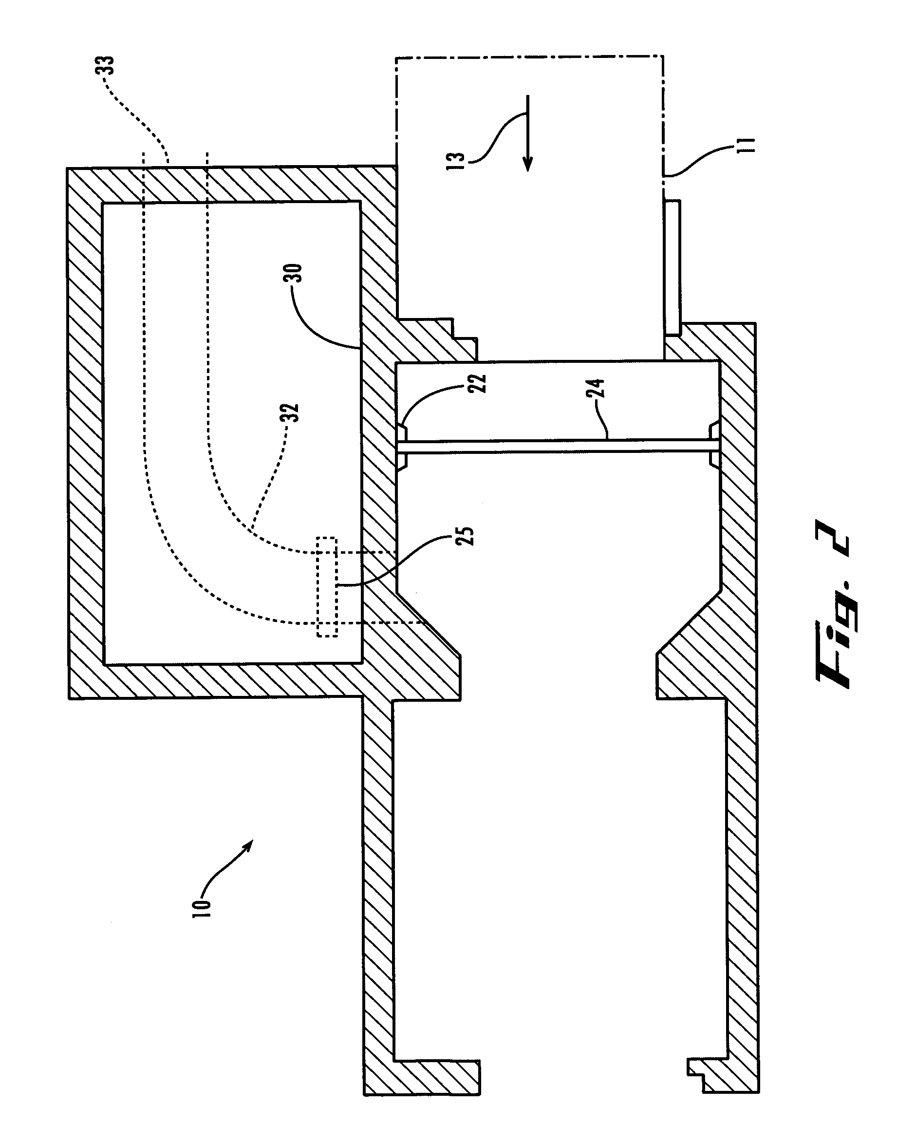
[0011]Referring to the drawings, wherein the like numerals designate corresponding parts throughout the several views, there is shown in FIGS. 1 and 2, a drainage installation 10 which is typically of concrete reinforced by steel rods or bars as is conventional. The installation 10 will have at its inlet an opening 9 to which will be connected to a drainage pipe 11. The opening 9 leads to a diversion chamber 14 in which is installed a baffle 24 and pivot mounts, one of which is shown at 22. As explained below, the pivot mounts, two of which are provided on opposite ends of a baffle support rod, allows the baffle 24 to pivot in the direction arrow 26 once a sufficient load is applied to the right hand face of the baffle 24 as viewed in FIG. 1. The diversion chamber 14 extends to the restriction 16 formed on the interior wall of the installation 10. Beyond the restriction 16, a tide gate chamber will be provided at 18. Normally, a weir 17 is placed across the restriction 16 to control...


PUM

PropertyMeasurementUnit
densityaaaaaaaaaa
hydraulic gradient forceaaaaaaaaaa
torqueaaaaaaaaaa

Abstract

A flow control baffle is suspended from a pivot shaft across a drain passage to restrict passage of waste material; the shaft is connected to a torque limiter which prevents rotation until a selected load is applied to the baffle upstream face; the torque limiter has a number of detent balls that are forced into detents by a series of springs acting thru a spring seat; increased flow increases torque on the baffle with the increasing torque transmitted through the baffle shaft and to the torque limiter. When the liquid reaches a preset level, the balls are forced out of the detents against the force of the springs and the baffle is free to rotate and float on the liquid surface. As the liquid level recedes, the baffle will return to its original vertical position, the balls will re-engage in the detents and lock the baffle in its original position and ready for the next cycle.

Description

CROSS-REFERENCE TO RELATED APPLICATIONS[0001]This application claims the benefit of provisional application No. 60 / 396,732 filed on Jul. 19, 2002.FIELD OF THE INVENTION[0002]The present invention relates to storm or drainage flow controls particularly where the flow is likely to include solids that must be segregated at least temporarily to permit downstream fluid handling operations to be carried out efficiently and safely.BACKGROUND OF THE INVENTION[0003]In many sewer and storm water drainage systems, modular parts of the system are constructed off site, transported and installed in a prepared site. Such preparation usually consists of excavation of an area to allow a contractor to quickly install and connect the prefabricated elements of the system. Such prefabrication reduces the costs of the system in terms of the portions used and the cost of installation. However, the design of the system cannot be easily modified due to the size of the prefabricated portions and the necessit...

Claims


Application Information

Patent Timeline
Patent Type & Authority Patents(United States)
IPC IPC(8): E03F5/12E03F5/00
CPCE03F5/12
Inventor FALLON, TIMOTHY Q.
Owner MUELLER INT LLC
Why Eureka
Try Eureka