Single chip ballast control with power factor correction

a single-chip ballast and power factor correction technology, applied in the direction of electric variable regulation, process and machine control, instruments, etc., can solve the problems of increasing the cost and size of the electronic ballast circuit, and posing a load control problem for fluorescent lamps, etc., to achieve low total harmonic distortion, simplify the ballast design, and high power factor

Inactive Publication Date: 2005-10-18
INFINEON TECH AMERICAS CORP
View PDF9 Cites 68 Cited by
  • Summary
  • Abstract
  • Description
  • Claims
  • Application Information

AI Technical Summary

Benefits of technology

[0018]The ballast control is fully integrated and capable of driving all types of fluorescent lamps. The PFC circuitry operates in critical conduction mode and provides high power factor, low total harmonic distortion, as well as DC bus regulation. The ballast control is programmable and includes programmable features including programmable preheat and r...

Problems solved by technology

Fluorescent lamps pose a load control problem to the power supply lines that provide lamp power, because the lamp load is non-linear.
By supplying power to output stage 22, bus capacitor Cbus is rated for high capacitance and high voltage operation, thereby increasing the cost and size of the electronic ballast circuit.
In addition, switches M1, M2 are also rated for h...

Method used


Image

  • Single chip ballast control with power factor correction
  • Single chip ballast control with power factor correction
  • Single chip ballast control with power factor correction

Examples


Embodiment Construction

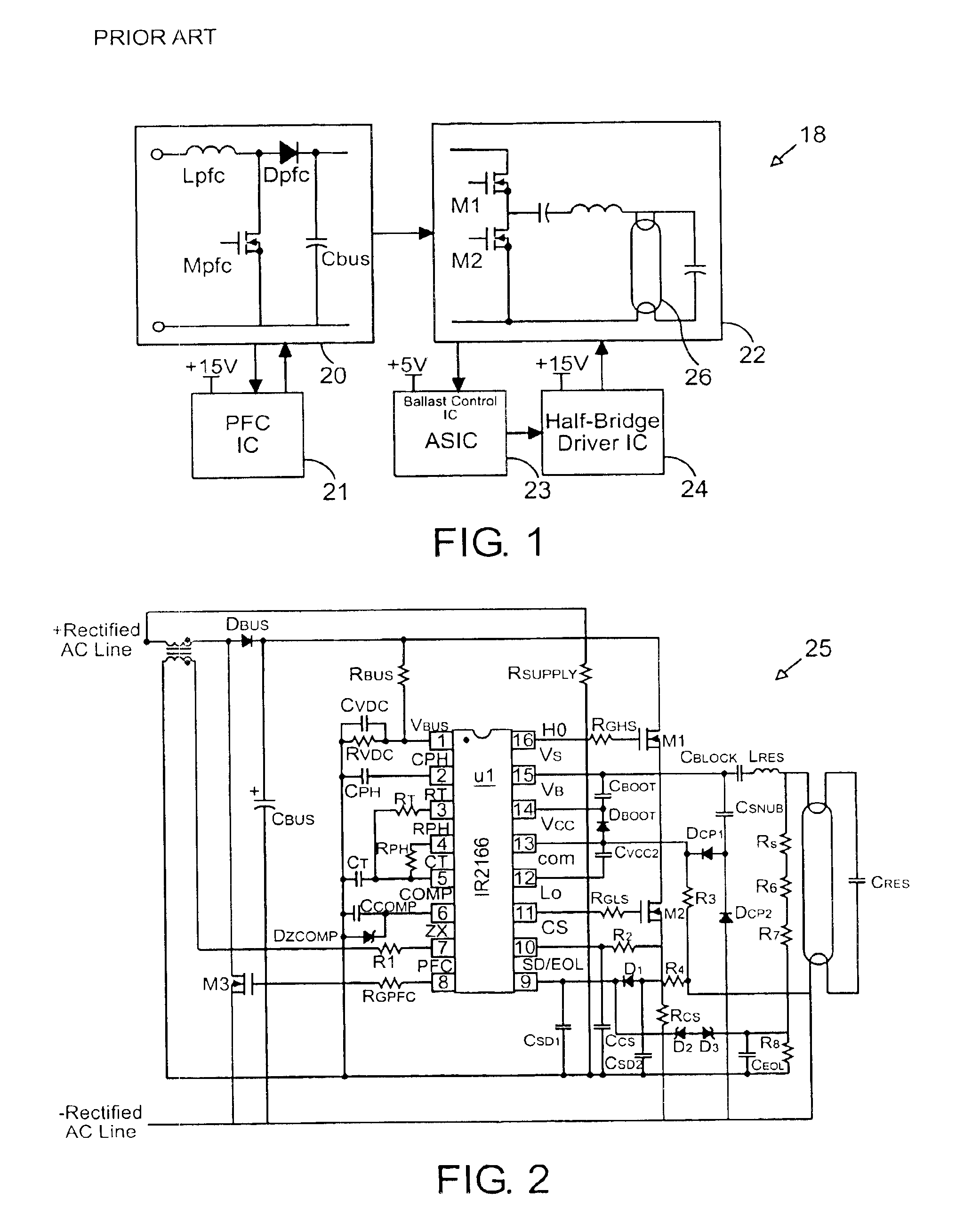
[0033]Referring now to FIG. 1, a conventional lamp ballast control circuit 18 is shown. Ballast circuit 18 is composed of two stages, a power factor correction (PFC) stage 20, and a lamp drive circuit stage 22. PFC stage 20 is controlled by an integrated circuit 21 and produces control signals for power factor correction. Ballast output stage 22 is controlled by a half-bridge driver integrated circuit 24. Driver 24 provides control signals to components in ballast output stage 22 to drive the ballast to provide appropriate lamp lighting control. Driver 24 also receives signals from a ballast control integrated circuit 23. Status and monitoring signals from ballast output stage 22 are directed to ballast control 23. With the feedback signals from ballast output stage 22, ballast control 23 derives control signals to feed to driver 24 to control ballast stage 22. In this conventional arrangement, PFC control, ballast control and half-bridge driver control are embodied in three separat...


PUM


Abstract

An integrated circuit provides a complete electronic ballast control with power factor correction for fluorescent lamps. The integrated circuit contains a simplified power factor correction (PFC) circuit to reduce component count and supply voltage requirements to reduce manufacturing costs while providing a robust control. The PFC circuit has a variable gain for fast response at high gain and optimized power factor control at low gain. An increased on time for the PFC switch when the input line voltage approaches zero dynamically reduces crossover distortion, thereby reducing total harmonic distortion. The integrated circuit incorporates a number of fault protections.

Description

RELATED APPLICATION[0001]The application is based on and claims benefit of U.S. Provisional Application No. 60 / 398,208, filed on Jul. 22, 2002, entitled Single Chip Ballast Control with Power Factor Correction, to which a claim of priority is hereby made.BACKGROUND OF THE INVENTION[0002]1. Field of the Invention[0003]The present invention relates generally to ballast controllers, and relates more particularly to ballast control for gas discharge lamps with power factor correction.[0004]2. Description of Related Art[0005]Ballasts have been used for many years as part of lighting systems and gas discharge lamps, and in particular for fluorescent lamps. Fluorescent lamps pose a load control problem to the power supply lines that provide lamp power, because the lamp load is non-linear. Current through the lamp is zero until an applied voltage reaches a starting value, at which point the lamp begins to conduct. As the lamp begins to conduct, the ballast ensures that the current drawn by ...

Claims


Application Information

Patent Timeline
IPC IPC(8): H05B41/298H05B41/28H02M3/155H05B41/24H02M7/12H05B41/282
CPCH05B41/2981H05B41/28
Inventor RIBARICH, THOMAS J.
Owner INFINEON TECH AMERICAS CORP
Why Eureka
Try Eureka