
Method for reducing ringing in NMR measurements by combining NMR signals having a spin echo and spurious signal component

Inactive Publication Date: 2005-10-18
SCHLUMBERGER TECH CORP
View PDF37 Cites 19 Cited by
  • Summary
  • Abstract
  • Description
  • Claims
  • Application Information

AI Technical Summary

Benefits of technology

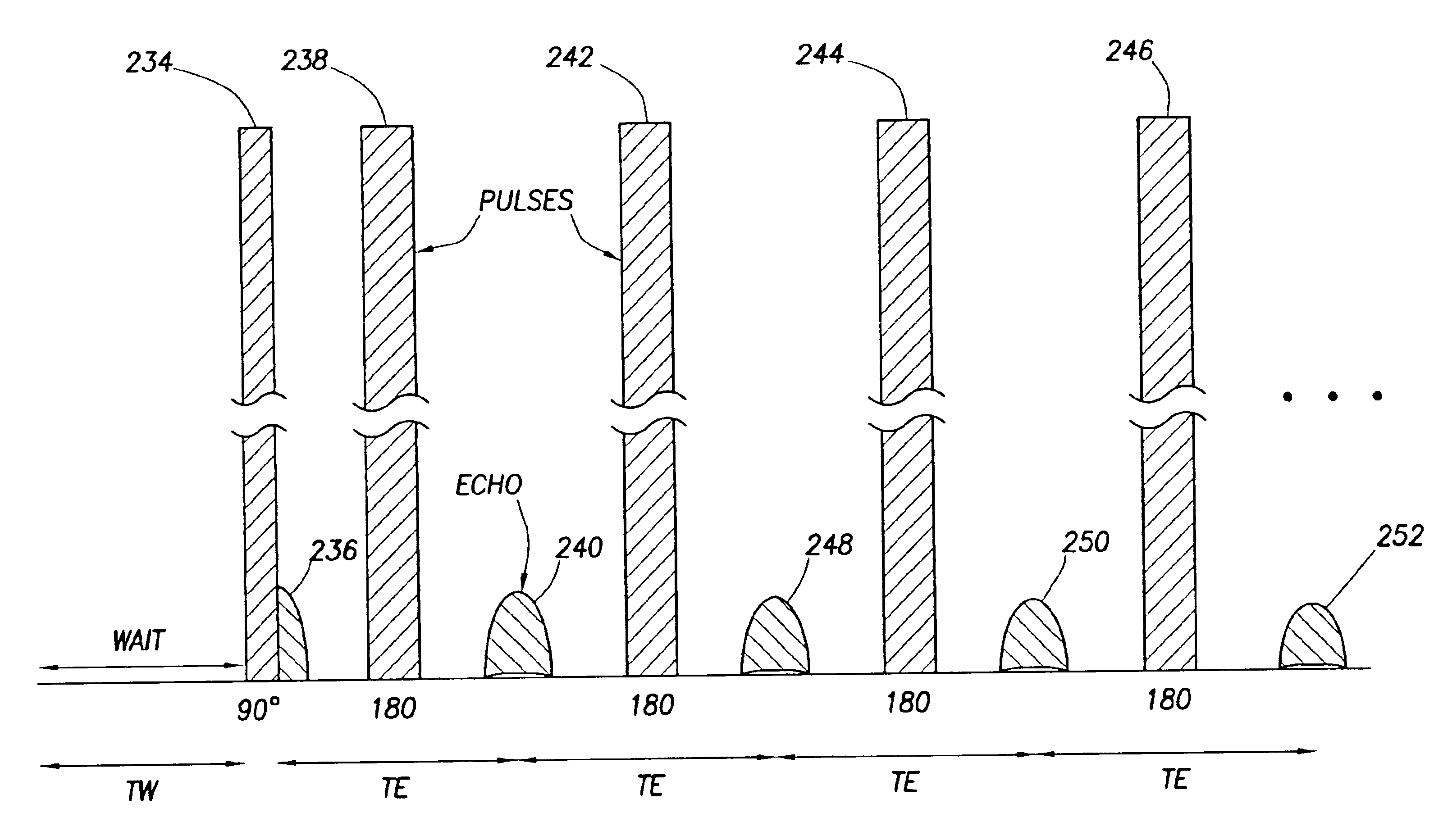
[0013]In accordance with another aspect of the invention, a method of reducing a ringing signal generated while measuring a nuclear magnetic resonance property of an earth formation adjacent a borehole is provided. The method comprises inserting a logging tool into the borehole, applying a static magnetic field to polarize spins within a volume of the formation, and applying an RF magnetic field to the volume in accordance with a pulse sequence having a plurality of pulses. After each of the plurality of pulses, spin echoes induced in the volume are acquired, thereby forming a measurement set comprising a plurality of spin echo signals, each of which includes a ringing component. The spin echo signals within the measurement set are combined to reduce the ringing components, thereby generating a corrected measurement set.

Problems solved by technology

The Carr-Purcell-like sequences, however, do not compensate for all undesirable artifacts appearing in NMR measurements.
Because the spin echoes typically are measured shortly after application of an RF pulse, the ringing signals often overwhelm the spin echo signals, resulting in loss of significant information regarding the formation properties.
However, because the 90 degree pulse is only applied once at the beginning of each sequence, its influence dies down relatively quickly and thus affects only early spin echo signals.
Thus, the phase alternating pair cancellation technique may not result in complete cancellation of the ringing signal in such applications.

Method used


Image

  • Method for reducing ringing in NMR measurements by combining NMR signals having a spin echo and spurious signal component
  • Method for reducing ringing in NMR measurements by combining NMR signals having a spin echo and spurious signal component
  • Method for reducing ringing in NMR measurements by combining NMR signals having a spin echo and spurious signal component

Examples


Embodiment Construction

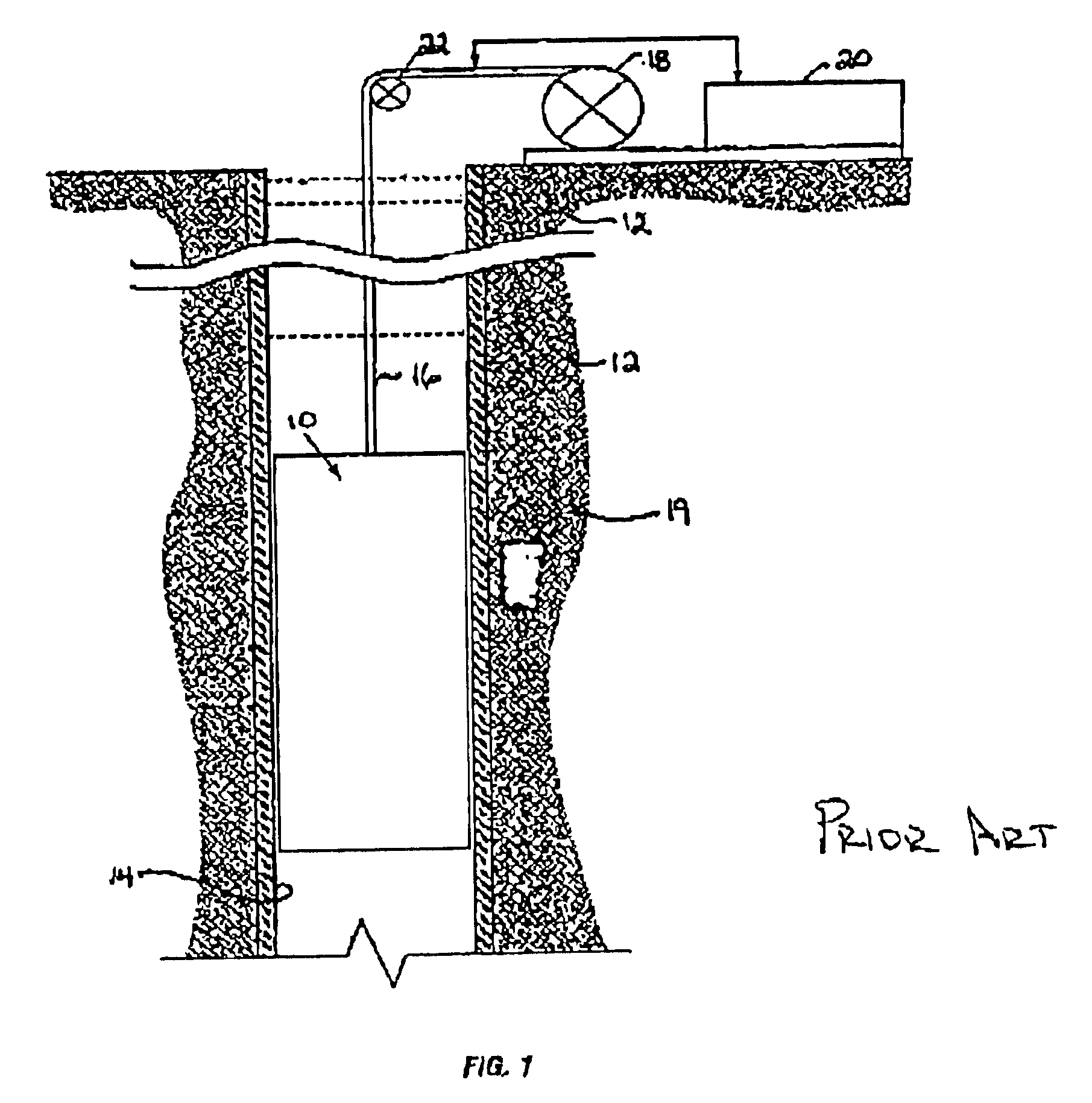
[0024]FIG. 1 illustrates a schematic of an exemplary nuclear magnetic resonance (NMR) well logging tool 10 for investigating one or more earth formations 12 traversed by a borehole 14. The logging tool 10 typically is suspended in the borehole 14 on an armored cable 16, the length of which substantially determines the relative depth of the logging tool 10. The cable length is controlled by any suitable means, such as a drum and winch arrangement 18 at the surface.

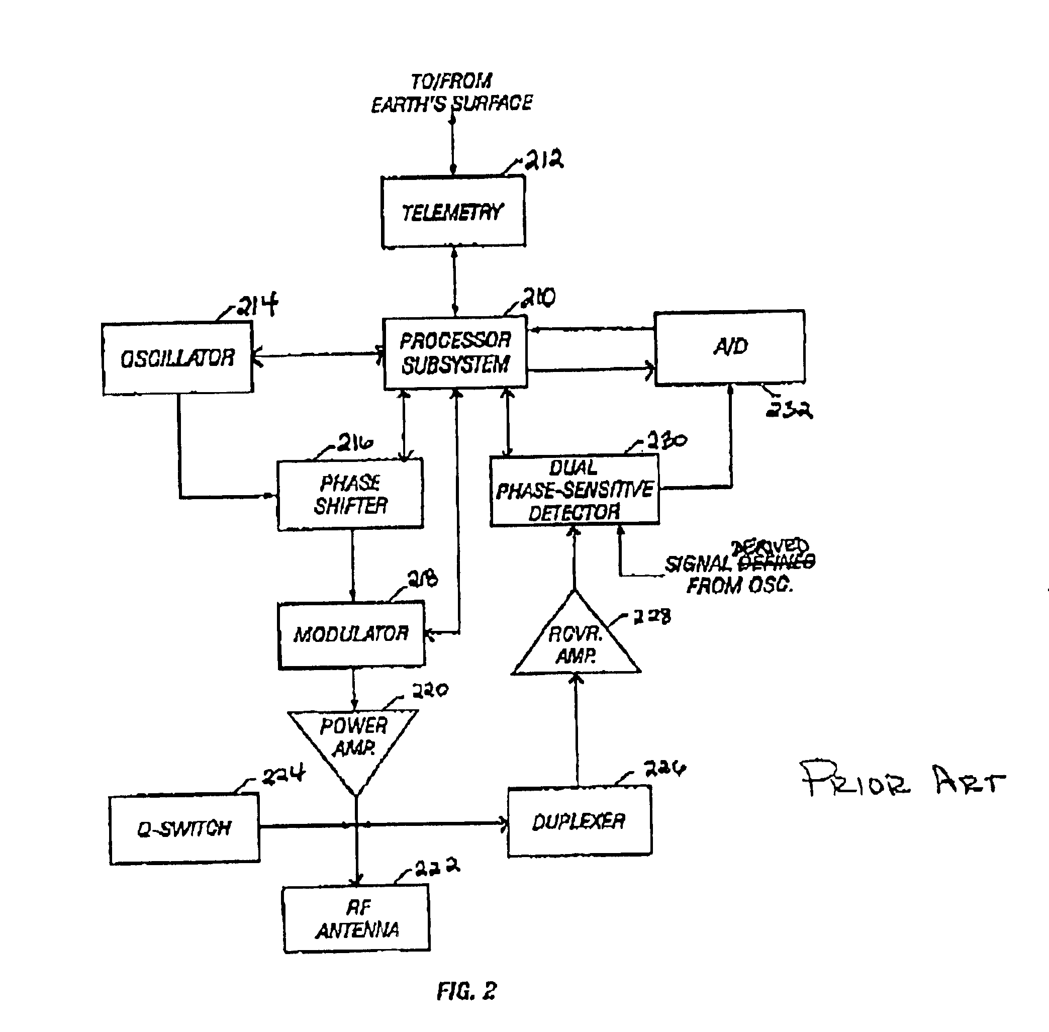
[0025]The NMR logging tool 10 can be any suitable downhole NMR logging device adapted for either wireline logging applications or logging-while-drilling (LWD) applications. As previously discussed, the logging tool 10 typically includes a permanent magnet, an electromagnet, or a magnet array for generating a static magnetic field B0 in a volume of interest 19 in the formations, one or more RF antennae (e.g., solenoid antennae, loop antennae, saddle antennae, etc.), and circuitry configured to produce pulses of RF power to i...


PUM


Abstract

A method of reducing ringing artifacts in a nuclear magnetic resonance measurement is provided. The method utilizes a new pulse sequence that offers ringing cancellation opportunities as well as compensation for otherwise accumulating spin dynamics errors. Ringing cancellation is accomplished by forming linear combinations of spin echoes induced as a result of the pulse sequence. Because the linear combinations are formed between closely spaced spin echoes (i.e., echoes within the same sequence), the likelihood that the ringing artifact will have changed between measurements is diminished.

Description

BACKGROUND OF INVENTION[0001]The present invention relates generally to a method for measuring nuclear magnetic resonance properties of an earth formation traversed by a borehole, and, more particularly, to a method for reducing ringing artifacts in a nuclear magnetic resonance measurement.[0002]Nuclear magnetic resonance (NMR) measurements taken in a borehole can provide different types of information about a geological formation. In the past, such measurements often were made after the borehole had been drilled. Today, however, it is possible to log NMR measurements while drilling (i.e., logging while drilling or LWD), thus saving time and providing valuable real-time information about the earth formation as drilling progresses. For example, such information can indicate the fractional volume of pore space, the fractional volume of mobile fluid, the total porosity of the formation, etc.[0003]NMR logging tools generally include one or more large permanent magnets or electromagnets ...

Claims


Application Information

Patent Timeline
IPC IPC(8): G01V3/32G01V3/18
CPCG01V3/32
Inventor HEIDLER, RALF
Owner SCHLUMBERGER TECH CORP
Learn More