Delay locked loop device

a technology of locking loop and dll device, which is applied in the direction of digital storage, pulse automatic control, instruments, etc., can solve the problems of power consumption problem of conventional dll device, equal phase error total phase error of dll device, etc., and achieve low jitter characteristic and consumption less power

Active Publication Date: 2005-10-18
SK HYNIX INC
View PDF9 Cites 56 Cited by
  • Summary
  • Abstract
  • Description
  • Claims
  • Application Information

AI Technical Summary

Benefits of technology

[0011]It is, therefore, an object of the present invention to provide a DLL device that consumes less power, and has low jitter characteristic.

Problems solved by technology

However, the conventional DLL device has a power consuming problem because two phase mixers (not shown), the two delay model units (140 and 160) and the two direct phase detectors (150 and 170) continue to operate after a delay value of the conventional DLL is locked.
In addition, since both the two delay lines continue to operate after the DLL is locked, a total phase error of the DLL device is equal to a phase error of one of the two delay lines.

Method used


Image

  • Delay locked loop device
  • Delay locked loop device
  • Delay locked loop device

Examples


Embodiment Construction

[0019]Hereinafter, a delay locked loop (DLL) device in accordance with the present invention will be described in detail referring to the accompanying drawings.

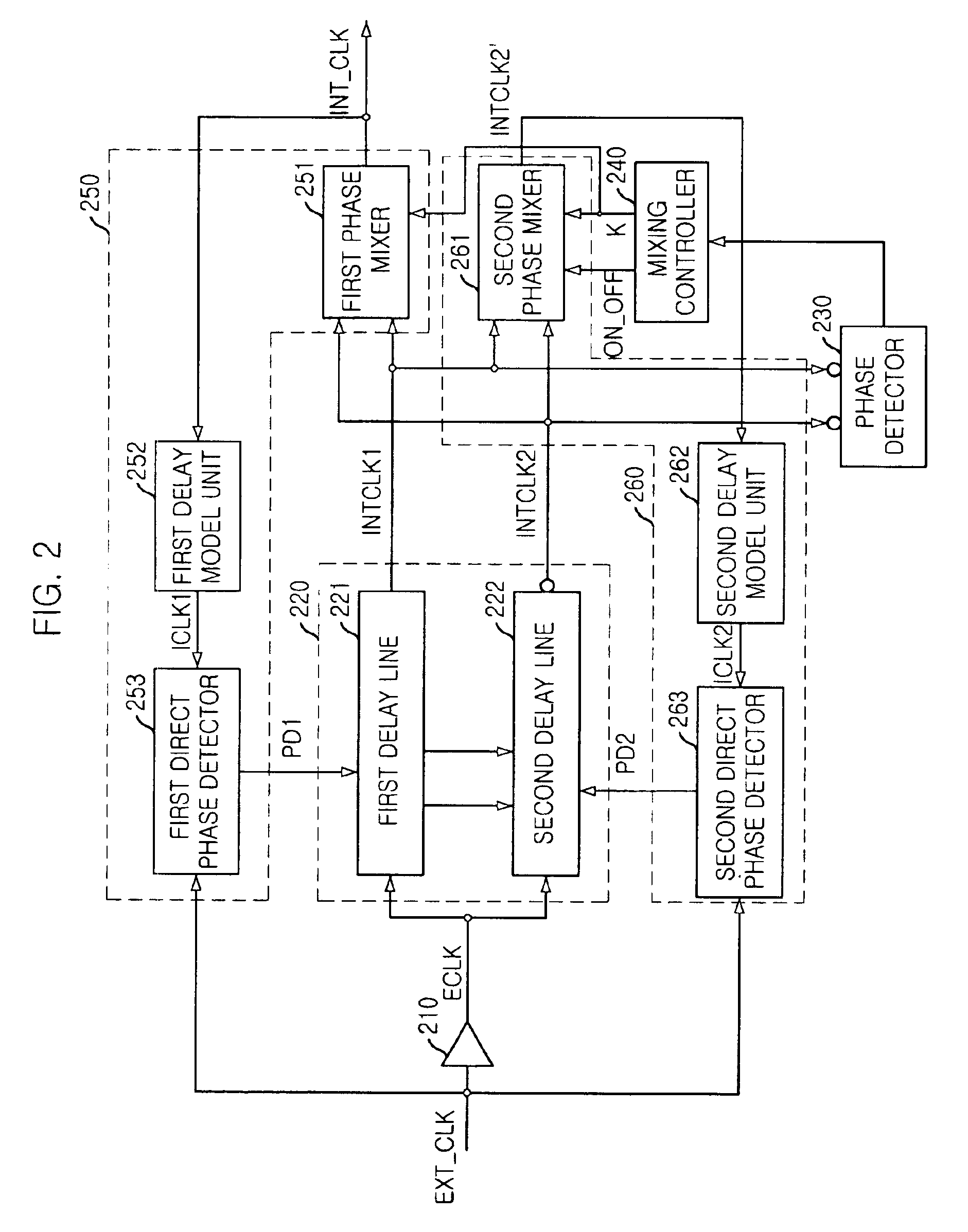
[0020]FIG. 2 is a block diagram showing the DLL device in accordance with the present invention.

[0021]As shown, the DLL device includes a buffer 210, a delay line unit 220, a phase detector 230, a mixing controller 240, a first delay control block 250 and a second delay control block 260.

[0022]The buffer 210 receives an external clock signal EXT_CLK to output an input clock signal ECLK to the delay line unit 220.

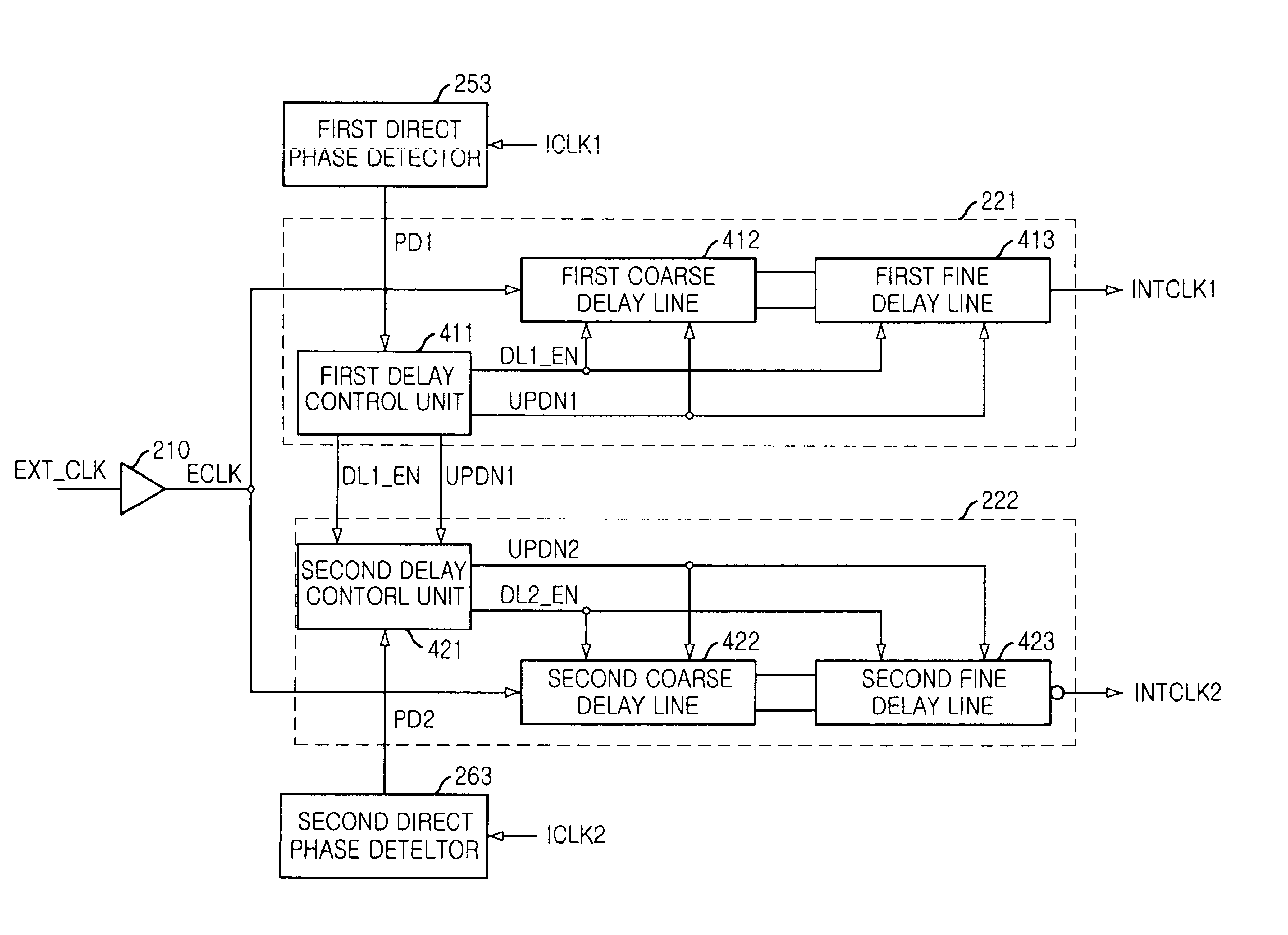
[0023]The delay line unit 220 includes a first delay line 221 and a second delay line 222. The 220 receives the input clock signal ECLK from the buffer 210, a first comparative signal PD1 from the first delay control block 250 and a second comparative signal PD2 from the second delay control block 260.

[0024]The first delay line 221 included in the delay line unit 220 receives the input clock signal ECLK and the first ...


PUM


Abstract

A delay locked loop device includes a first delay line for receiving an external clock signal and a first delay control signal to generate a first internal clock signal; a second delay line for receiving the external clock signal and a second delay control signal or the first delay control signal to generate a second internal clock signal; a first delay control block for receiving the external clock signal to generate the first delay control signal; a second delay control block for receiving the external clock signal to generate the second delay control signal; and a phase detecting block for receiving the first internal clock signal and the second internal clock signal to generate the on-off signal by comparing a phase of the first internal clock signal with a phase of the second internal clock signal.

Description

FIELD OF INVENTION[0001]The present invention relates to a delay locked loop (DLL) device; and, more particularly, to a DLL device which synchronizes an internal clock signal with an external clock signal.DESCRIPTION OF PRIOR ART[0002]A delay locked loop (DLL) device is used for a synchronous semiconductor memory device to synchronize an internal clock signal with an external clock signal. Since there is a time delay while the external clock is inputted to the synchronous semiconductor memory device, the DLL device is needed for synchronizing the internal clock signal with the external clock signal.[0003]FIG. 1 is a block diagram showing a conventional DLL device disclosed in a commonly owned copending application, U.S. Ser. No. 10 / 331,412, filed on Dec. 30, 2002, entitled “DIGITAL DLL APPARATUS FOR CORRECTING DUTY CYCLE AND METHOD THEREOF”, which is incorporated herein by reference.[0004]The conventional DLL device includes a buffer 110, a delay line unit 120, a duty error control ...

Claims


Application Information

Patent Timeline
Patent Type & Authority Patents(United States)
IPC IPC(8): H03L7/087H03L7/08H03L7/06H03K5/04H03K5/05H03L7/081G11C11/407H03L7/07
CPCH03L7/07H03L7/0802H03L7/0814H03L7/087H03L7/0818H03L7/0816H03L7/08
Inventor KWAK, JONG-TAELEE, SEONG-HOON
Owner SK HYNIX INC
Why Eureka
Try Eureka