
Network structure using high dispersion volume holography

Inactive Publication Date: 2005-10-18
COMMISSARIAT A LENERGIE ATOMIQUE ET AUX ENERGIES ALTERNATIVES
View PDF6 Cites 23 Cited by
  • Summary
  • Abstract
  • Description
  • Claims
  • Application Information

AI Technical Summary

Benefits of technology

[0014]To achieve this, one objective of the invention is to supply a grating structure by volume holography with high dispersive power, such that, in particular, it can be introduced in a Treacy type arrangement and which in addition displays very good stretching or compression efficiency as well as better resistance to laser flow than the diffraction gratings of the prior art.

Problems solved by technology

However, they do not offer complete satisfaction.
A disadvantage with engraved gratings is that their throughput, approximately 90%, only results in a low compression efficiency, approximately 65%.
Another disadvantage of these engraved gratings is that they display poor resistance to the laser flow.
Consequently, users equipped with installations producing considerable energy are unable, in practice, to fully benefit from all the power they would expect from an efficient compressor and / or stretcher.

Method used


Image

  • Network structure using high dispersion volume holography
  • Network structure using high dispersion volume holography
  • Network structure using high dispersion volume holography

Examples


Embodiment Construction

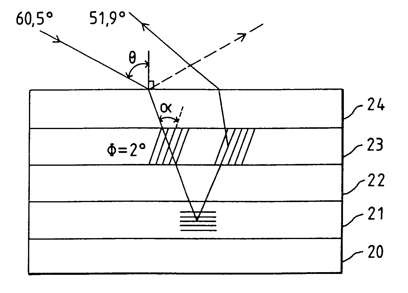
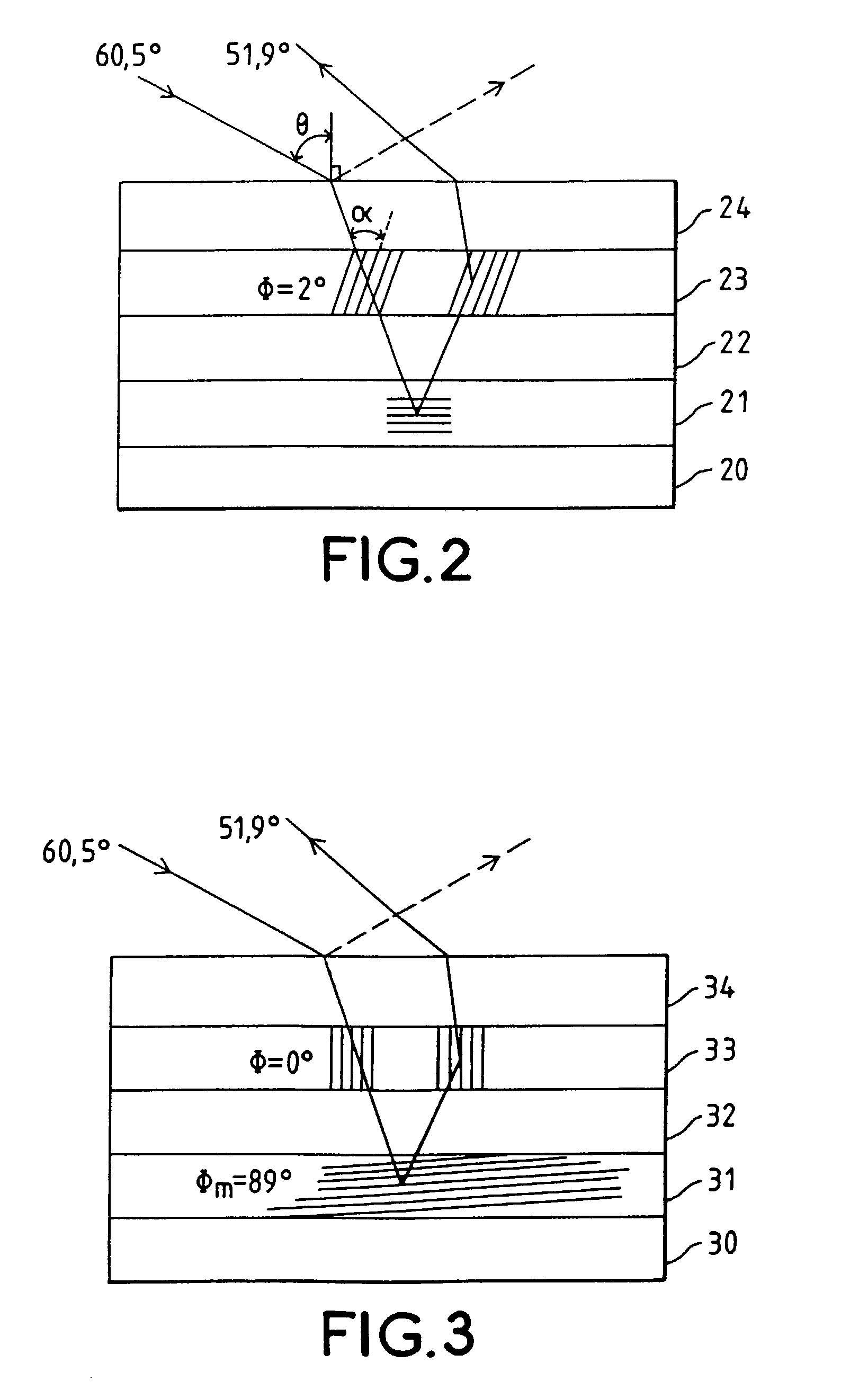
[0024]The grating structure according to the invention comprises in particular a transmission volume holographic grating produced on a reflective support. The volume grating is formed from a thick layer (a few dozen microns) of a holographic material in which strata of given pitch Λ are inscribed, inclined with respect to the plane of the layer support at a given angle φ defined with respect to the normal to the support. The angle of inclination φ and the pitch of the strata Λ are chosen such that a light beam of given mean central wavelength λ0, incident on the said structure with a given angle of incidence θ, undergoes a first passage through the grating, is reflected by the reflective support, undergoes a second passage through the grating and is only diffracted by the grating during one of the said passages. In practice, since the angle of incidence of the beam is given (preferably close to the Brewster angle to avoid reflections at the interface), the pitch of the strata is det...


PUM


Abstract

A grating structure by high dispersion volume holography that applies, for example, to pulse compression or stretching devices. The grating structure includes a transmission volume holographic grating produced on a reflective support. The grating includes strata inclined to the plane of the support, the angle of inclination of the strata defined with respect to the normal to the support and the pitch of the strata being chosen such that a light beam of a predetermined mean wavelength, incident on the structure with a predetermined angle of incidence, undergoes a first passage through the grating, is reflected by the reflective support, undergoes a second passage through the grating, and is only diffracted by the grating during one of the first and second passages.

Description

BACKGROUND OF THE INVENTION[0001]1. Field of the Invention[0002]The invention concerns a grating structure by high dispersion volume holography. It applies in particular in pulse compression or stretching devices, e.g. for the production of ultrashort or very high energy laser pulses. It also applies in the field of optical telecommunications, e.g. for wavelength division multiplexing devices or wave trap devices.[0003]2. Discussion of the Background[0004]In the fields of physics and chemistry, numerous analyses and many types of processing require the use of very short, high-energy laser pulses. For example, very powerful laser pulses are required in the field of plasma physics. Pulses with very high peak power are also useful in the field of machining materials, since they result in cleaner and more accurate contours, by reducing the heating of the materials machined.[0005]To date, the production of very high peak power laser pulses (Tera or Peta Watts) uses the CPA (Chirped Pulse...

Claims


Application Information

Patent Timeline
IPC IPC(8): G02B5/32G02B5/18G03H1/02
CPCG02B5/32G03H1/0248G03H2001/2231G03H2001/2234G03H2001/2615
Inventor MORBIEU, BERTRANDLABORIE, JEAN-JACQUES
Owner COMMISSARIAT A LENERGIE ATOMIQUE ET AUX ENERGIES ALTERNATIVES
Features
  • Generate Ideas
  • Intellectual Property
  • Life Sciences
  • Materials
  • Tech Scout
  • Unparalleled Data Quality
  • Higher Quality Content
  • 60% Fewer Hallucinations
Learn More