Optical blocking filter having an array of micro-mirrors

a micro-mirror and optical blocking technology, applied in the field of dynamic optical filters, can solve the problems of large diffraction losses, unchannel plan independent, and high cost of 40 or 80 channel devices

Inactive Publication Date: 2005-10-18
II VI DELAWARE INC
View PDF26 Cites 58 Cited by
  • Summary
  • Abstract
  • Description
  • Claims
  • Application Information

AI Technical Summary

Benefits of technology

[0011]An object of the present invention is to provide a pixilated optical blocking filter having a spatial light modulator that includes a micro-mirror device having an array of micro-mirrors, wherein a plurality of micro-mirrors, actuated in concert, eliminates a selected channel, a specified selection of channels, or selected bands of channels by deflecting the light beam constituting the optical channels away from the return path. The present invention effectively meets the requirements of a blocking filter by

Problems solved by technology

One disadvantage of Bragg grating technology is that it requires many discrete gratings and/or switches, which makes a 40 or 80 channel device quite expensive.
One issue with the above optical MEMs device is that it is not

Method used


Image

  • Optical blocking filter having an array of micro-mirrors
  • Optical blocking filter having an array of micro-mirrors
  • Optical blocking filter having an array of micro-mirrors

Examples


Embodiment Construction

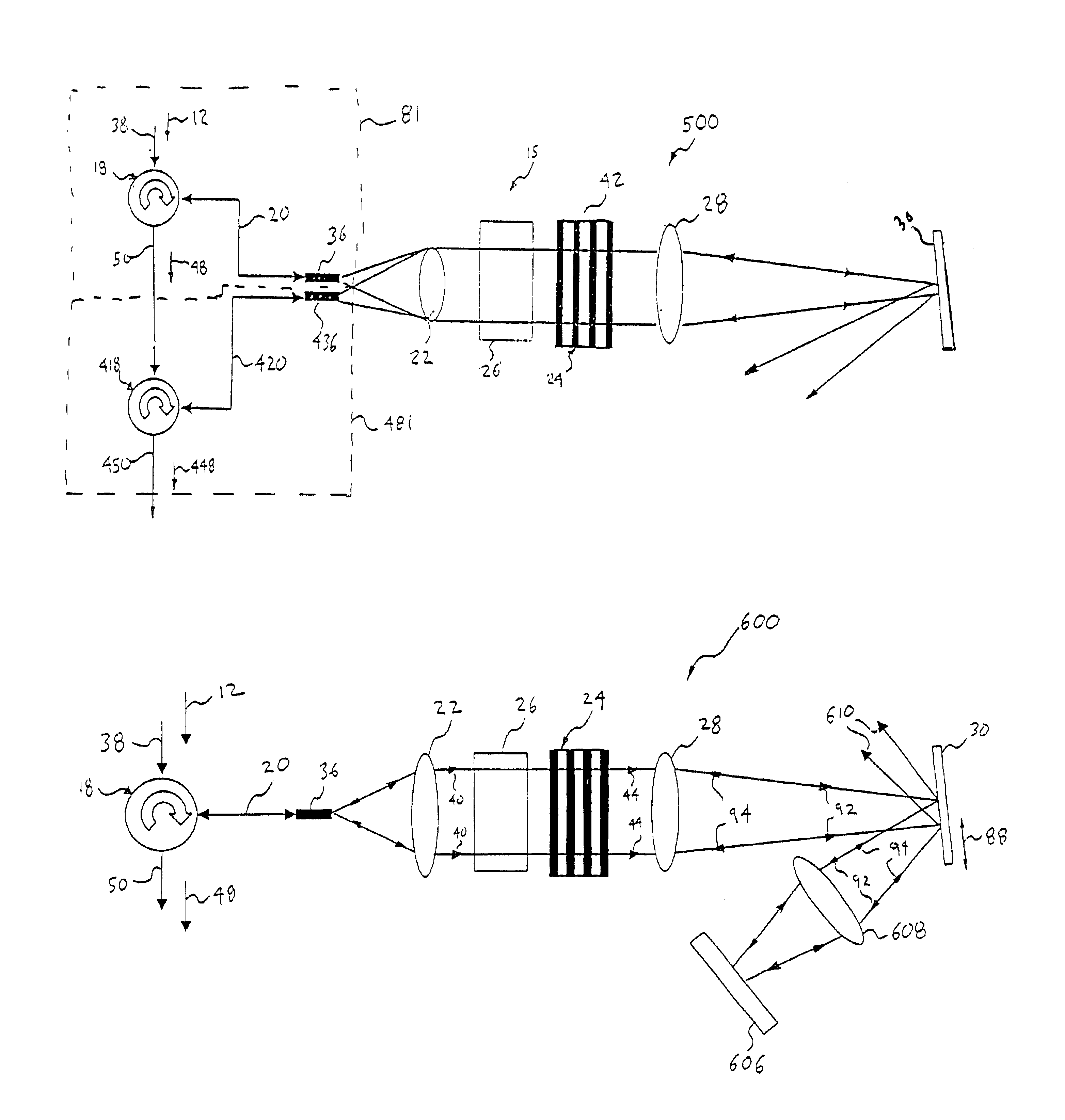
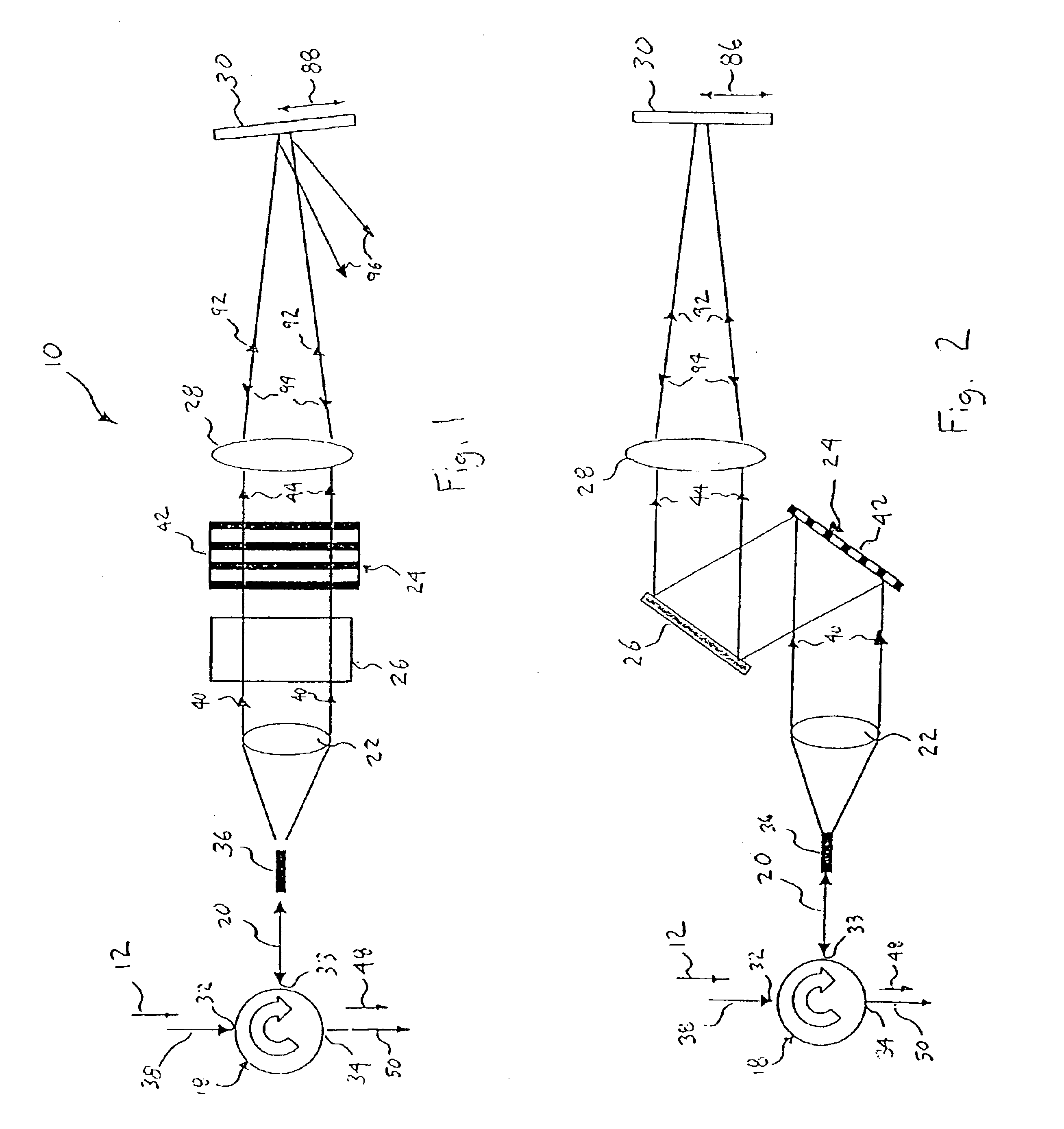
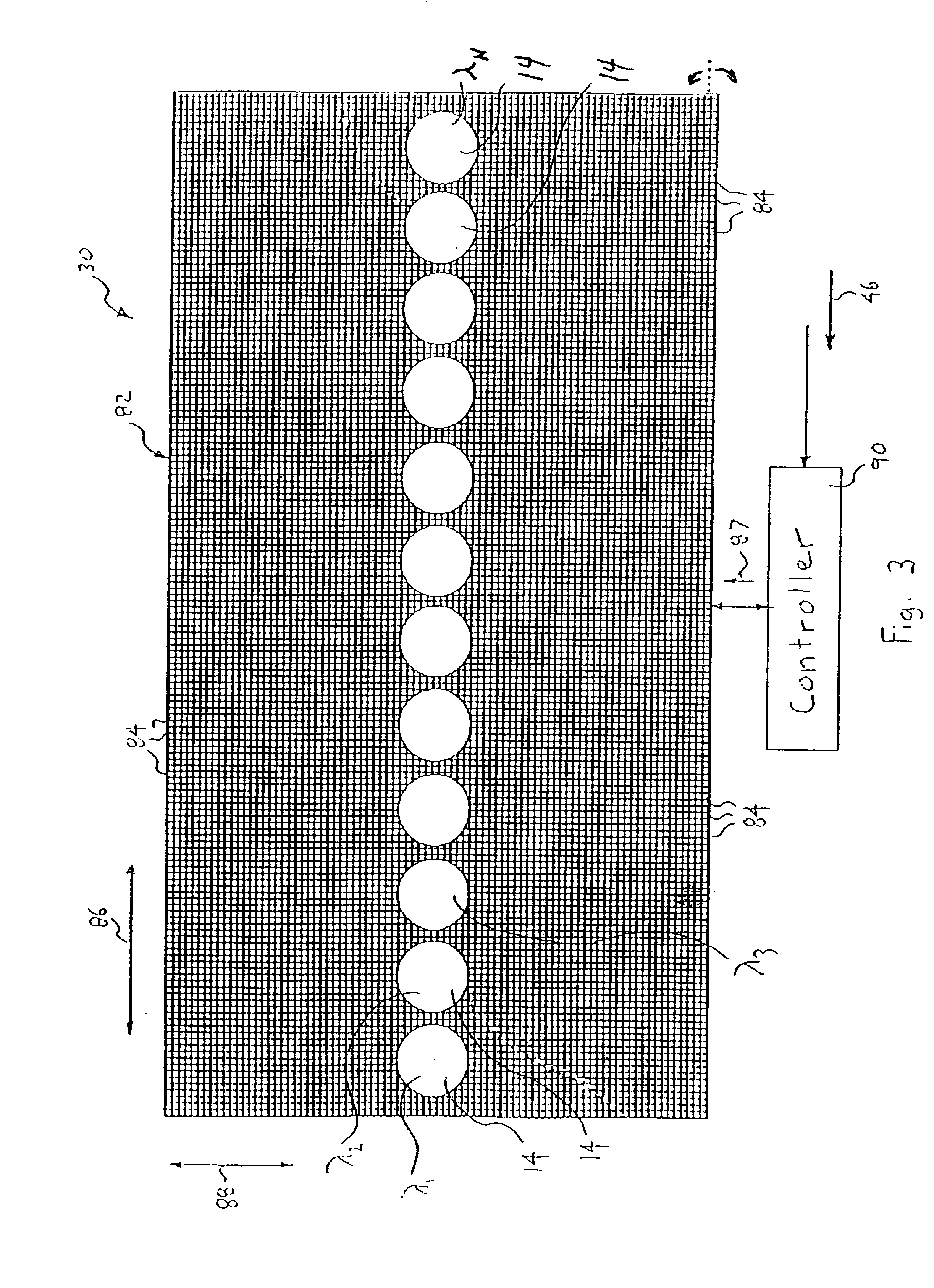
[0050]Referring to FIGS. 1-3, an optical blocking filter, generally shown as 10, deletes at least one desired optical channel 14 of light (i.e., a wavelength band) from an optical WDM input signal 12. Each of the optical channels 14 (see FIG. 3) of the input signal 12 is centered at a respective channel wavelength (λ1, λ2, λ3, . . . , λN)

[0051]FIG. 1 is a top plan view of the blocking filter 10. To better understand the blocking filter 10 of FIG. 1, a side elevational view of the blocking filter is illustrated in FIG. 2. As shown in FIG. 2, the optics of the blocking filter 10 is disposed in two tiers or horizontal planes. Specifically, the blocking filter includes a three-port circulator 18, an optical fiber or pigtail 20, a collimator 22, a light dispersive element 24, a mirror 26, and a bulk lens 28 for directing light to and from a spatial light modulator 30. As shown, the pigtail 20, the collimator 22 and the light dispersive element 24 are disposed in a first tier or horizonta...


PUM


Abstract

A reconfigurable optical blocking filter deletes a desired optical channel(s) from an optical WDM input signal, and includes a spatial light modulator having a micro-mirror device with a two-dimensional array of micro-mirrors that tilt between first and second positions in a “digital” fashion in response to a control signal provided by a controller in accordance with a switching algorithm and an input command. A collimators, diffraction grating, and Fourier lens, collectively collimate, separate and focus the optical input channels onto the array of micro-mirrors. The optical channel is focused on the micro-mirrors onto a plurality of micro-mirrors of the micro-mirror device, which effectively pixelates the optical channels. To delete an input channel of the optical input signal, micro-mirrors associated with each desired input channel are tilted to reflect the desired input channel away from the return path.

Description

CROSS REFERENCE TO RELATED APPLICATIONS[0001]This patent claims the benefit to U.S. Provisional Patent Application Ser. No. 60 / 332,318, filed Nov. 16, 2001, and is a continuation-in-part of U.S. patent application Ser. No. 10 / 115,647, filed Apr. 3, 2002, which claims the benefit of U.S. Provisional Patent Application Ser. No. 60 / 281,079, filed Apr. 3, 2001; U.S. Provisional Patent Application Ser. No. 60 / 311,002, filed Aug. 8, 2001; U.S. Provisional Patent Application Ser. No. 60 / 332,319, filed Nov. 16, 2001; U.S. Provisional Patent Application Ser. No. 60 / 365,741, filed Mar. 18, 2002; and U.S. Provisional Patent Application Ser. No. 60 / 365,461, filed Mar. 18, 2002; and is a continuation-in-part of U.S. patent application Ser. No. 10 / 120,617, filed Apr. 11, 2002, now abandoned, which claims the benefit of U.S. Provisional Patent Application Ser. No. 60 / 283,197, all of which are incorporated herein by reference in their entirety.BACKGROUND OF THE INVENTION[0002]1. Technical Field[000...

Claims


Application Information

Patent Timeline
IPC IPC(8): G02B26/08G02B27/10G02B6/34G02B6/26H04J14/02G02B6/42H04Q11/00
CPCG02B6/262G02B6/266G02B6/29394G02B26/0833G02B26/0841G02B27/1086H04J14/0212H04J14/0213H04J14/0221G01J3/021G01J3/0229G02B6/4226H04Q2011/0009H04Q2011/0026Y10S359/904
Inventor MOON, JOHN A.KERSEY, ALAN D.SIRKIS, JAMES S.DUNPHY, JAMES R.PINTO, JOSEPHSZCZEPANEK, PAULDAVIS, MICHAEL A.PUTNAM, MARTIN A.
Owner II VI DELAWARE INC
Why Eureka
Try Eureka