Current controlled contact arc suppressor

a current control and contact arc technology, applied in the circuit field, can solve the problems of electrical arc formation between the contacts and damage to the contact terminal, and achieve the effect of preventing arcing

Inactive Publication Date: 2005-10-18
SCHWEITZER ENGINEERING LABORATORIES
View PDF5 Cites 33 Cited by
  • Summary
  • Abstract
  • Description
  • Claims
  • Application Information

AI Technical Summary

Benefits of technology

[0006]Accordingly, the present invention is a circuit for suppression of arcing between electrical contacts, comprising: a transistor connected across the contacts; a control circuit for controlling the operation of the transistor, wherein turning on the transistor results in a current path around the contacts, which tends to prevent arcing between...

Problems solved by technology

It is a well-known problem that when the flow of current to an inductive load through a switch or relay contacts is either interrupted or initiated (such as by opening or closing and subsequent bouncing of the switch), the energy in the inductive load is transferred ...

Method used


Image

  • Current controlled contact arc suppressor
  • Current controlled contact arc suppressor

Examples


Embodiment Construction

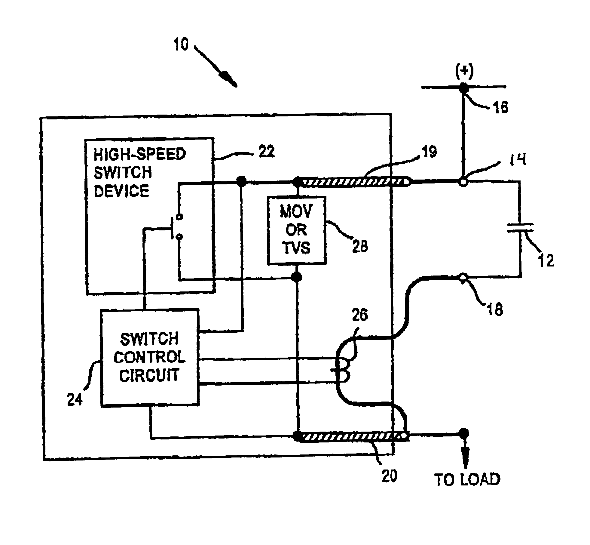
[0009]In general, the present invention uses an inductance, in particular, a saturable flyback transformer in the embodiment shown, and the current therethrough, which is positioned in series with the contact terminals which are connected to the load to control an arc suppression circuit for the contacts.

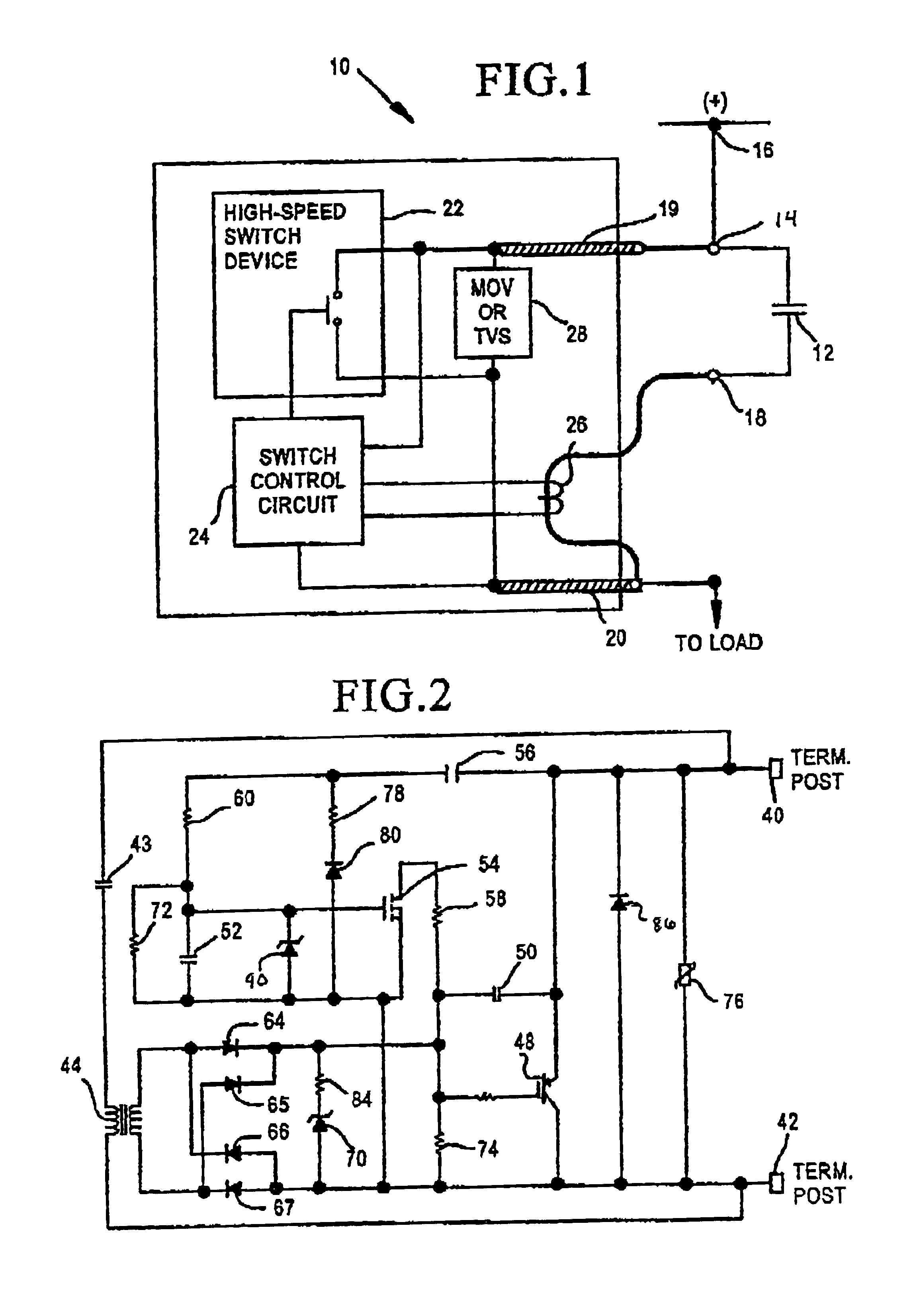
[0010]The flyback transformer stores energy when the contact terminals are closed. When the terminals open, the energy in the flyback transformer is transferred to a capacitor connected to the secondary of the transformer very quickly in a flyback action. The voltage on the capacitor is used to power a switch control circuit, which assists in turning the protection transistor connected across the contacts on and maintaining it on. A small amount of additional “Miller capacitance” is used to help turn on the protection transistor faster than otherwise. Generally, this invention may be used with all kinds of shunt (by-pass) transistors. The basic electrical circuit which controls the ...


PUM


Abstract

The arc suppression system for electrical contacts includes a transistor, such as an IGBT, which is connected across the contacts. A control circuit controls the operation of the transistor such that the turning on of the transistor results in a current path around the contacts, thereby tending to prevent arcing across the contacts. A current sensor, such as a flyback transformer, is positioned in series with the contacts, wherein when the contacts open, current is interrupted through the contacts and the transformer, a secondary voltage results which is applied to the transistor, which tends to maintain the transistor on for a time which is sufficient to allow the contacts to either open or close without an arc.

Description

TECHNICAL FIELD[0001]This invention relates generally to a circuit for suppression of arcing between two electrical contacts, and more particularly concerns such a protection circuit which makes use of the current through the contacts to control the arc suppression circuit, following either the opening or closing of the electrical contacts.BACKGROUND OF THE INVENTION[0002]It is a well-known problem that when the flow of current to an inductive load through a switch or relay contacts is either interrupted or initiated (such as by opening or closing and subsequent bouncing of the switch), the energy in the inductive load is transferred to a voltage spike, which causes an electrical arc to form between the contacts. This arcing damages the contact terminals.[0003]There are numerous patents which attempt to remedy or lessen the effect of the above-described condition. U.S. Pat. No. 5,703,743 to Lee, which is owned by the assignee of the present invention; U.S. Pat. No. 4,658,320 to Hong...

Claims


Application Information

Patent Timeline
IPC IPC(8): H01H9/54
CPCH01H9/542H01H2009/543H01H2009/544
Inventor BOUGHTON, JR., DONALD H.LEE, TONY J.
Owner SCHWEITZER ENGINEERING LABORATORIES
Why Eureka
Try Eureka