High accuracy receiver forward and reflected path test injection circuit

a receiver and forward reflection technology, applied in the field of wireless communication systems, can solve the problems of increasing the cost of bts, increasing the number of base transceiver stations, and increasing infrastructure costs, and achieves the effects of increasing accuracy, high accuracy of receiving signal strength indicators, and high accuracy of calibration methods for rf receive antennas

Inactive Publication Date: 2005-10-18
SAMSUNG ELECTRONICS CO LTD
View PDF10 Cites 8 Cited by
  • Summary
  • Abstract
  • Description
  • Claims
  • Application Information

AI Technical Summary

Benefits of technology

[0020]It is an object of the present invention to provide for use in an RF receiver unit a test injection circuit for accurately measuring RF signals within the RF receiver unit.
[0021]It is another object of the present invention to provide for use in an RF receiver unit a test injection circuit for accurately measuring RF signals that comprises a circulator coupled to an antenna of the RF receiver unit and an injection source coupled to the circulator that is capable of injecting a test RF signal into the circulator.
[0022]It is also an object of the present invention to provide a circulator within the RF receive path of an RF receiver unit that has a rev

Problems solved by technology

Accordingly, the greater number of base transceiver stations increases infrastructure costs.
Unfortunately, adding some types of test equipment (e.g., spectrum analyzers) to a BTS significantly increases the cost of the BTS.
In some cases, the cost of the test equipment may be greater than the cost of the BTS itself.
As a result, wireless service providers may not install any test equipment in the ETS.
Alternatively, wireless service providers may install only

Method used


Image

  • High accuracy receiver forward and reflected path test injection circuit
  • High accuracy receiver forward and reflected path test injection circuit
  • High accuracy receiver forward and reflected path test injection circuit

Examples


Embodiment Construction

[0033]FIGS. 1 through 4, discussed below, and the various embodiments used to describe the principles of the present invention in this patent document are by way of illustration only and should not be construed in any way to limit the scope of the invention. Those skilled in the art will understand that the principles of the present invention may be implemented in any suitably arranged wireless network.

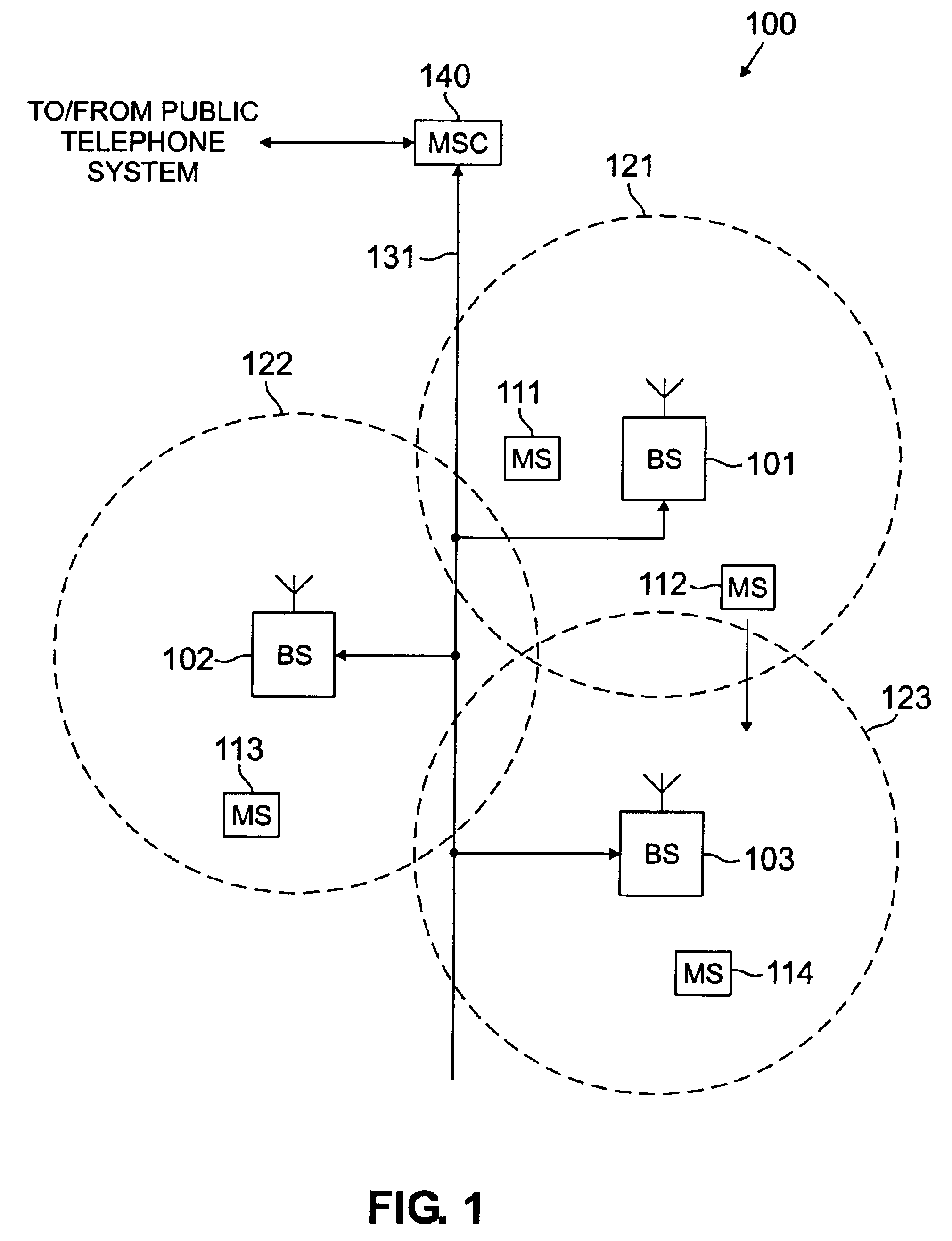
[0034]FIG. 1 illustrates an exemplary wireless network 100 according to one embodiment of the present invention. The wireless telephone network 100 comprises a plurality of cell sites 121-123, each containing one of the base stations, BS 101, BS 102, or BS 103. Base stations 101-103 are operable to communicate with a plurality of mobile stations (MS) 111-114. Mobile stations 111-114 may be any suitable cellular devices, including conventional cellular telephones, PCS handset devices, portable computers, metering devices, and the like.

[0035]Dotted lines show the approximate boundaries ...


PUM


Abstract

There is disclosed an injection circuit for measuring radio frequency (RF) signals in an RF receiver for use in measuring the impedance match of a receive antenna and for use in calibrating receiver gain, wherein an advantageous embodiment of the injection circuit comprises: 1) a circulator coupled to the receive antenna; 2) a directional coupler coupled to the circulator; 3) an injection source coupled to the circulator and to the directional coupler, wherein the injection source is capable of injecting a test RF signal into either the circulator or the directional coupler; and 4) a terminating switch for selectively enabling or disabling the transfer of a test RF signal from the injection source to either the circulator or the directional coupler. The circulator has a reverse isolation of at least 20 dB that significantly increases the accuracy of the measurements of the RF signals compared with the accuracy that may be achieved by prior art methods. The present invention obtains the received signal strength indicator (RSSI) measurements at any instantaneous temperature and operating channel and determines voltage standing wave ratio (VSWR) measurements.

Description

CROSS-REFERENCE TO RELATED APPLICATIONS[0001]This application is a continuation of prior U.S. patent application Ser. No. 09 / 564,927 filed on May 4, 2000 now U.S. Pat. No. 6,704,352.[0002]The present invention is related to that disclosed in U.S. patent application Ser. No. 09 / 475,604, filed Dec. 30, 1999, entitled “COMBINED SYSTEM FOR CALIBRATING RECEIVER GAIN AND MEASURING ANTENNA IMPEDANCE MATCH AND METHOD OF OPERATION.” Application Ser. No. 09 / 475,604 is commonly assigned to the assignee of the present invention. The disclosure of the related patent application is hereby incorporated by reference in the present application as if fully set forth herein.TECHNICAL FIELD OF THE INVENTION[0003]The present invention is directed, in general, to wireless communications systems and, more specifically, to radio frequency (RF) test injection circuits for measuring the antenna impedance match of a receive antenna and measuring receiver gain in a base station in a wireless network.BACKGROUND...

Claims


Application Information

Patent Timeline
IPC IPC(8): H04B17/00
CPCH04B17/20H04B17/0085H04B17/21H04B17/318
Inventor JOHNSON, MITCHELL K.
Owner SAMSUNG ELECTRONICS CO LTD
Why Eureka
Try Eureka