Ultra-fast adder

a technology of adders and adders, applied in the field of digital logic, can solve the problems of significant reduction of the switching speed of the corresponding logic circuit, increase parasitic capacitance, and reduce the speed of the gb>3/b> circuit b>300/b>, and achieve the effect of greater performance advantage and balanced operation

Inactive Publication Date: 2005-10-18
ORACLE INT CORP
View PDF3 Cites 8 Cited by
  • Summary
  • Abstract
  • Description
  • Claims
  • Application Information

AI Technical Summary

Benefits of technology

[0012]A method and apparatus are disclosed that increase the speed of carry look-ahead (CLA) adders by reducing the stack height of their first stage logic circuits. In accordance with the present invention, a CLA adder capable of adding (or subtracting) two input signals includes first stage logic having a plurality of carry-create and carry-transmit logic circuits each coupled to receive one or more bits of each input signal. Each carry-create circuit generates a novel carry-create signal in response to corresponding first bit-pairings of the input signals, and each carry-transmit circuit generates a novel carry-transmit signal in response to corresponding second bit-pairings of the input signals. The carry-create and carry-transmit signals are combined in CLA logic to generate accumulated carry-create signals, which are then used to select final sum bits.
[0014]In addition, Applicant's carry-create and carry-transmit logic circuits have evenly balanced discharge paths. For one embodiment, each discharge path in the carry-create logic circuit includes two stacked input transistors, and each discharge path in the carry-transit logic circuit includes three stacked input transistors. As a result, Applicant's carry-create and carry-transmit logic circuits do not require transistor sizing adjustments to maintain balanced operation, which may result in an even greater performance advantage over prior art CLA adders.

Problems solved by technology

Because of the well-known body effect phenomenon, the addition of each stacked input transistor significantly reduces the switching speed of the corresponding logic circuit.
However, increasing the size of transistors 306-309 in an effort to achieve balanced operation also increases parasitic capacitances, which in turn further reduces the speed of G3 circuit 300.

Method used


Image

  • Ultra-fast adder
  • Ultra-fast adder
  • Ultra-fast adder

Examples


Embodiment Construction

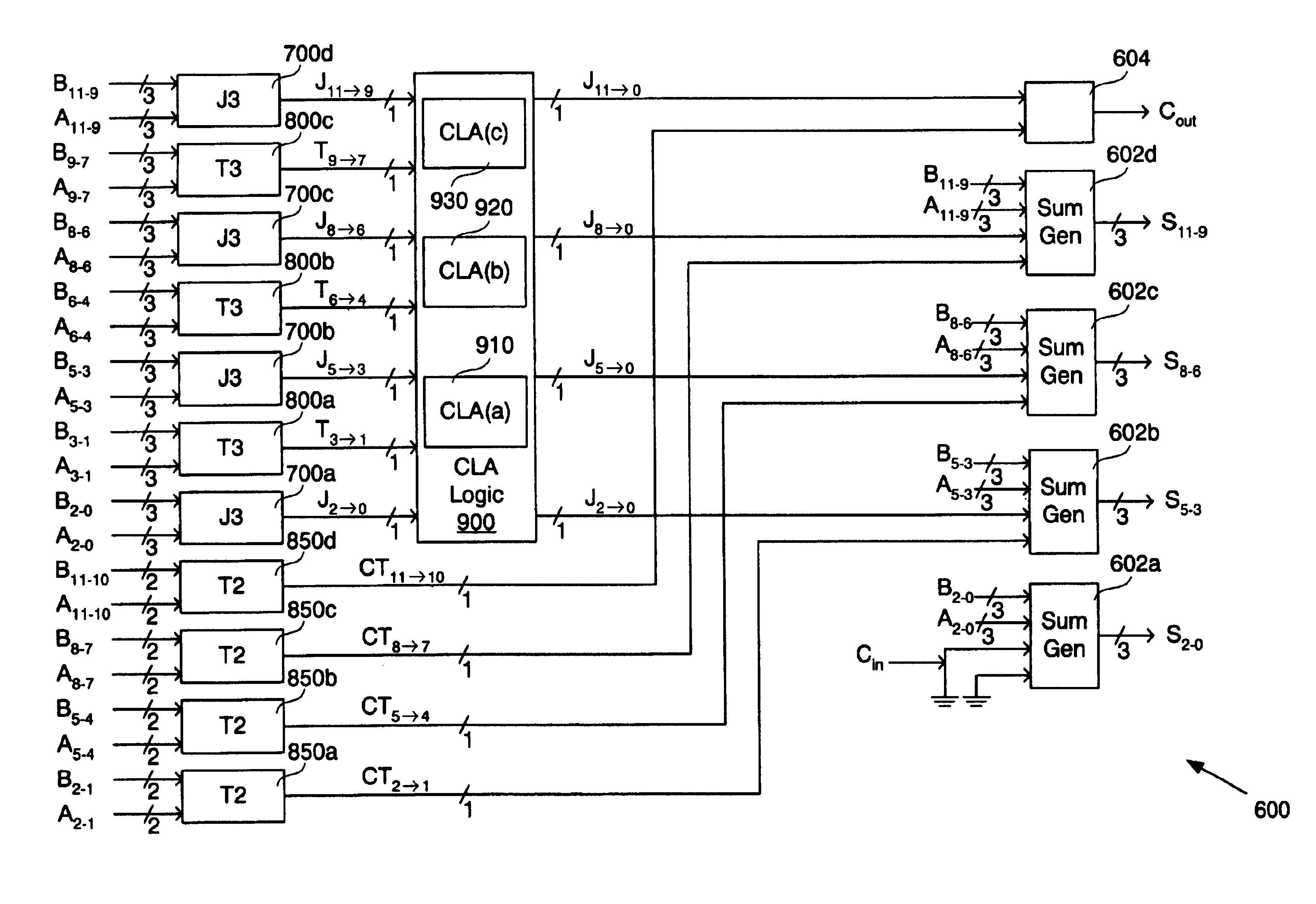
[0029]Present embodiments are discussed below in the context of a 12-bit adder 100 for simplicity only. It is to be understood that present embodiments are equally applicable to adders that combine input signals of other various bit lengths. Further, although described below in the context of dynamic logic, embodiments of the present invention may be implemented in static logic. Also, the specific configurations of logic circuits disclosed for implementing various logical expressions described in accordance with the present invention may be modified as desired. In addition, adders of the present invention may be readily used to perform arithmetic subtraction operations. Accordingly, the present invention is not to be construed as limited to specific examples described herein but rather includes within its scope all embodiments defined by the appended claims.

[0030]FIG. 6 is a block diagram of one embodiment of a 12-bit bit carry look-ahead (CLA) adder 600 in accordance with the prese...


PUM


Abstract

A carry look-ahead adder capable of adding or subtracting two input signals includes first stage logic having a plurality of carry-create and carry-transmit logic circuits each coupled to receive one or more bits of each input signal. Each carry-create circuit generates a novel carry-create signal in response to corresponding first bit-pairings of the input signals, and each carry-transmit circuit generates a novel carry-transmit signal in response to corresponding second bit-pairings of the input signals. The carry-create and carry-transmit signals are combined in carry look-ahead logic to generate accumulated carry-create signals, which are then used to select final sum bits.

Description

BACKGROUND[0001]1. Field of Invention[0002]This invention relates generally to digital logic and specifically to carry-look ahead adders.[0003]2. Description of Related Art[0004]FIG. 1 is a block diagram of a conventional 12-bit carry look-ahead adder 100 having three processing stages in which input signals A[11:0] and B[11:0] are logically combined to generate a 12-bit sum signal S[11:0] and a carry-out bit Cout. In the first stage, groups of three input signal pairs are combined in conventional 3-bit propagate circuits (P3) 200 and 3-bit generate circuits (G3) 300 to produce well-known carry-propagate P[z→x] and carry-generate signals G[z→x], respectively. Specifically, each carry-propagate circuit 200 logically combines three bit-pairings of the input signals A[z:x] and B[z:x] to generate its carry-propagate signal P[z→x] according to the well-known logical expression P[z→x]=(Ax+Bx)|(Ay+Bz)|(Az+Bz), where | denotes the logical AND operation and + denotes the logical OR operation...

Claims


Application Information

Patent Timeline
Patent Type & Authority Patents(United States)
IPC IPC(8): G06F7/50G06F7/48G06F7/508
CPCG06F7/507G06F7/508G06F2207/3872
Inventor TAM, HONKAI
Owner ORACLE INT CORP
Why Eureka
Try Eureka