Safety valve, in particular for cooking plate gas and related mounting method

a safety valve and gas burner technology, applied in the direction of combustion process, combustion ignition, heating fuel, etc., can solve the problems of high cost of valves such as these, gas used as fuel to produce, and require safety devices, so as to simplify the design and manufacture of setting devices

Inactive Publication Date: 2005-10-25
BURNER SYST INT BSI
View PDF7 Cites 2 Cited by
  • Summary
  • Abstract
  • Description
  • Claims
  • Application Information

AI Technical Summary

Benefits of technology

[0012]It is an object of the invention to propose a fuel supply valve comprising a setting device that is simple and reliable to operate, for converting the control movement, for example vertical, of a control rod into a setting movement, for example horizontal, for the safety device.
[0016]Making the lever from bent sheet metal makes it possible to guarantee a small cross section perpendicular to the direction of gas flow, that is to say transversely with respect to the supply circuit. This cross section and the small pressure drops it creates means that the supply circuit need not be oversized in order to allow the gaseous mixture to flow therein under satisfactory conditions.
[0018]Aside from the small pressure drops created, the reduced cross section makes it possible to give the lever a certain elasticity, particularly in terms of torsion about an axis perpendicular to this section. This elasticity can be put to several uses, particularly for keeping the lever preloaded between the setting command and the shutter, so that the transmission of the command is without play and gives fluidity in the command, and therefore is comfortable for the user. This elasticity can also be used to absorb certain manufacturing tolerances and therefore to reduce the cost of manufacture of the valve while at the same time ensuring that it operates safely.
[0021]To guarantee the position of the lever in the cavity when fitting the shut-off stopper, precentering means may be provided on the lever for precentering the lever in the cavity. These precentering means keep the posterior end of the lever in a position close to the theoretical axis, which position allows it to collaborate with the self-centering means of the stopper, when the latter is being fitted, when the lever is no longer accessible from outside the valve body. This arrangement allows the lever to be mounted “blind” in the cavity. As a preference, the self-centering means in the closed end of the cavity and on the stopper will act as bearings for the rotation of the setting lever, this having the purpose of simplifying the design and manufacture of the setting device.

Problems solved by technology

The gases used as fuel to produce energy, and which when mixed with air under certain conditions produce explosive mixtures, are dangerous and require the use of safety devices.
A valve such as this is expensive and its setting device is delicate in proportion to its complexity.
Such a device also has disadvantages.
Further, as one ramp does not bear on the other axially, it generates radial forces and wear in bearings for guiding them and the rubbing-together of the ramps causes them both to wear.
This wear may cause valve malfunction.
This demands both high precision in the manufacture of the setting lever and of its arms, which makes it an expensive part, and in the adjustment of the parts during assembly, which increases the cost of manufacture.
Significant friction leads therefore to high costs of manufacture of these parts.

Method used


Image

  • Safety valve, in particular for cooking plate gas and related mounting method
  • Safety valve, in particular for cooking plate gas and related mounting method
  • Safety valve, in particular for cooking plate gas and related mounting method

Examples


Embodiment Construction

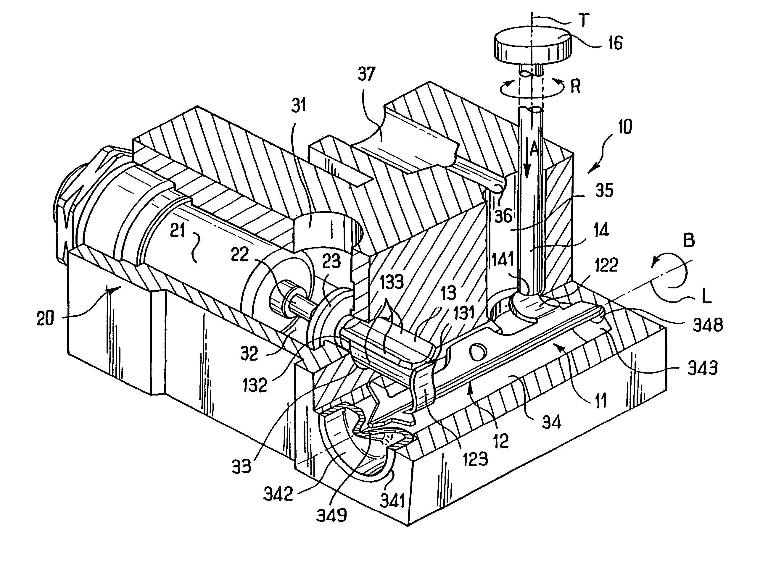
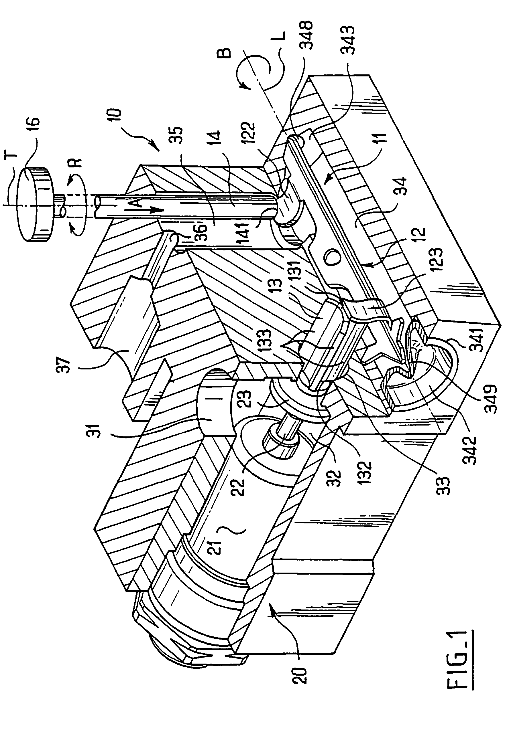
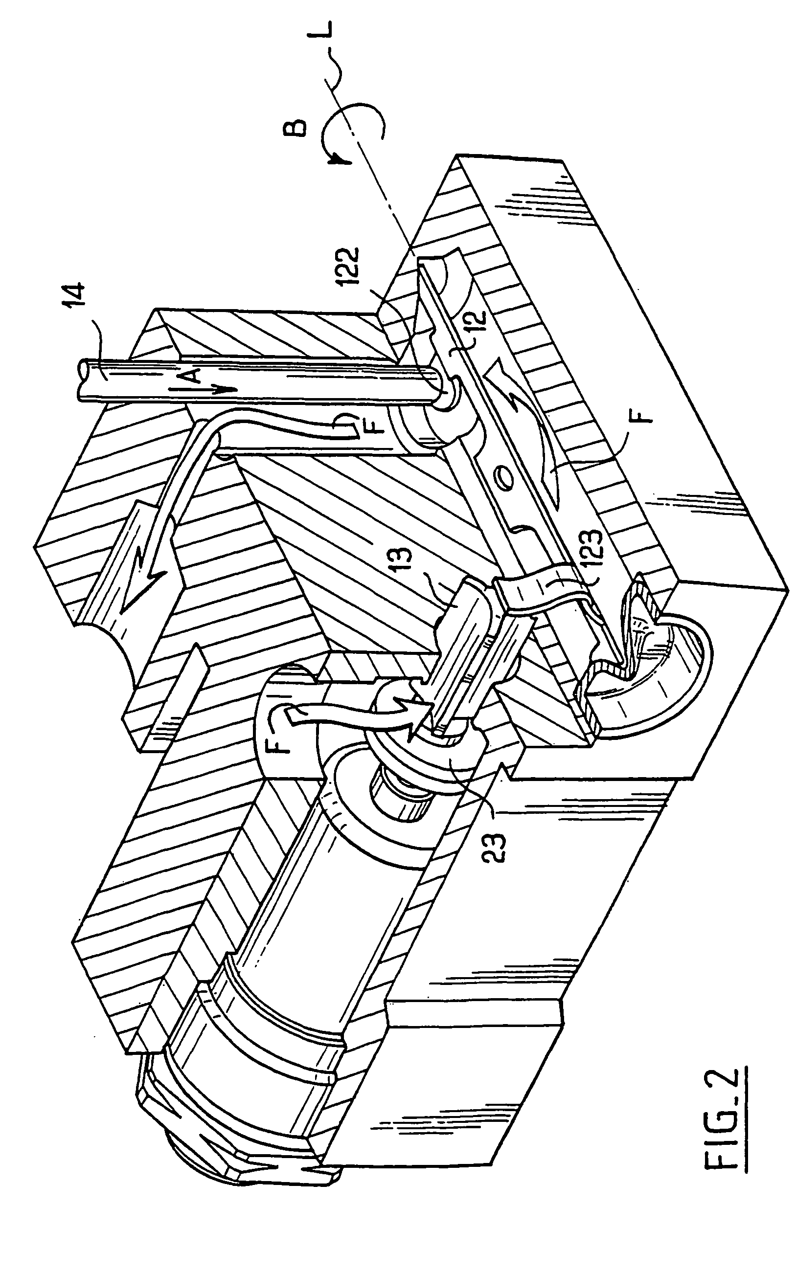
[0027]FIGS. 1 and 2 depict, in section and in perspective, a body 10 of a safety valve according to the invention, designed to be mounted in a hob using gas. The body comprises a safety device 20 mounted in a gas supply circuit. The safety device 20 is depicted in a closed position in FIG. 1, that is to say that it prevents gas from flowing through the supply circuit. The safety device 20 is depicted in an open position in FIG. 2.

[0028]The supply circuit comprises, in succession, in the body 10, an inlet pipe 31 letting gas into an inlet chamber 32, a safety orifice 33 at the intersection of the inlet chamber and of an intermediate cavity 34, the intermediate cavity, a regulating chamber 35, a regulating orifice 36 and a gas outlet 37 for the outlet of gas to a burner, not depicted.

[0029]The body 10 is output as a section piece the section of which is tailored to the shape of the body, that is to say that the section piece is output transversely in slices the thickness of which is m...


PUM


Abstract

The invention concerns a safety gas valve (1) provided with a safety closure (23) and an operating lever (12) for the closure. The lever (12) is mounted mobile in rotation about an axis L in a cavity (34) circulating the gas and comprises two tabs (122, 123) extending transversely to the axis L, one driving and the other driven. The driving tab (122) drives the lever in rotation, and hence the driven tab (123) which is secured thereto, in response to a stress A when the valve is opened. The driven tab (123) enables to push back the safety closure (23) into an opening position allowing the gas to flow in the valve. If both tabs extend along respective mutually perpendicular directions, the lever (12) enables the cocking movement to return by 90 degrees. Said device reduces the thickness of the valve body, in particular for its fixing into a built-in cooking plate.

Description

BACKGROUND OF THE INVENTION[0001]The present invention relates to improvements made to safety devices for gas burners, particularly in a cooking appliance, and particularly those suited to be mounted on a built-in hob equipped with gas burners. The invention is aimed more specifically at improving a safety device for a gas burner according to the preamble of claim 1.[0002]The gases used as fuel to produce energy, and which when mixed with air under certain conditions produce explosive mixtures, are dangerous and require the use of safety devices. In particular, valves for cooking appliances employing gas burners, in addition to having a flow-regulating control valve for the gas, are also equipped with such devices. These in particular allow the gas supply to be cut off as soon as the gas is not being burnt in a burner.[0003]These safety devices generally employ a thermocouple, arranged in the burner, to monitor its correct operation and a safety shutter which, in the event of failur...

Claims


Application Information

Patent Timeline
Patent Type & Authority Patents(United States)
IPC IPC(8): F23N5/02F23N5/10
CPCF23N5/107Y10T137/1516
Inventor CHOINARD, PHILIPPE
Owner BURNER SYST INT BSI
Why Eureka
Try Eureka