Dispense tip with vented outlets

Inactive Publication Date: 2005-10-25
DL TECH
View PDF112 Cites 44 Cited by
  • Summary
  • Abstract
  • Description
  • Claims
  • Application Information

AI Technical Summary

Benefits of technology

[0012]In a first aspect, the present invention is directed to a cartridge adapted for use with a fluid pump. The cartridge includes a material inlet port, a material outlet port, a feed screw, and a reservoir. The feed screw is disposed longitudinally through the body of the cartridge for delivering fluid provided at the inlet port to the outlet port. The inlet port takes the form of an elongated port provided at a side portion of the feed screw proximal to allow for fluid provided at the inlet port. This elongated configuration promotes even distribution of fluid during transport by the feed screw, and lowers system pressure, thereby reducing the likelihood of “balling-up” and/or clogging of fluid.
[0013]The inlet port is preferably provided through the cartridge body at an acute angle relative to the reservoir to allow for gravity-assisted fluid delivery. The inner portion of the cartridge may be lined with a carbide or plastic (for example Teflon, torlon, or tercite) liner having an aperture aligned with the inlet port to enhance ease of cleaning. The elongated port of the cartridge may be provided in a wall of the carbide liner.
[0014]In another aspect, the present invention is directed to a release bracket for mounting the syringe and cartridge to the body of the pump. In this manner, the syringe, feed tube, and cartridge can be dismantled from the pump body as a unit, allowing for joint storage of the syringe, feed tube and cartridge, while minimizing risk of contamination of the material. Additionally, once the system is initially purged of extraneous gas during initialization, the purged system can be stored as a unit without the need for re-initializati

Problems solved by technology

Such conventional pump systems suffer from several limitations.
The motor and rotary clutch mechanisms are bulky and heavy, and are therefore limited in application for modern dispensing applications requiring increasingly precise, efficient, and fast operation.
The excessive weight limits use for those applications that require contact of the pump with the substrate, and limits system speed and accuracy, attributed to the high g-forces required for quick movement of the system.
The mechanical clutch is difficult to control, and coasts to a stop when disengaged, resulting in deposit of excess fluid.
However, the spring adds to the lengt

Method used


Image

  • Dispense tip with vented outlets
  • Dispense tip with vented outlets
  • Dispense tip with vented outlets

Examples


Example

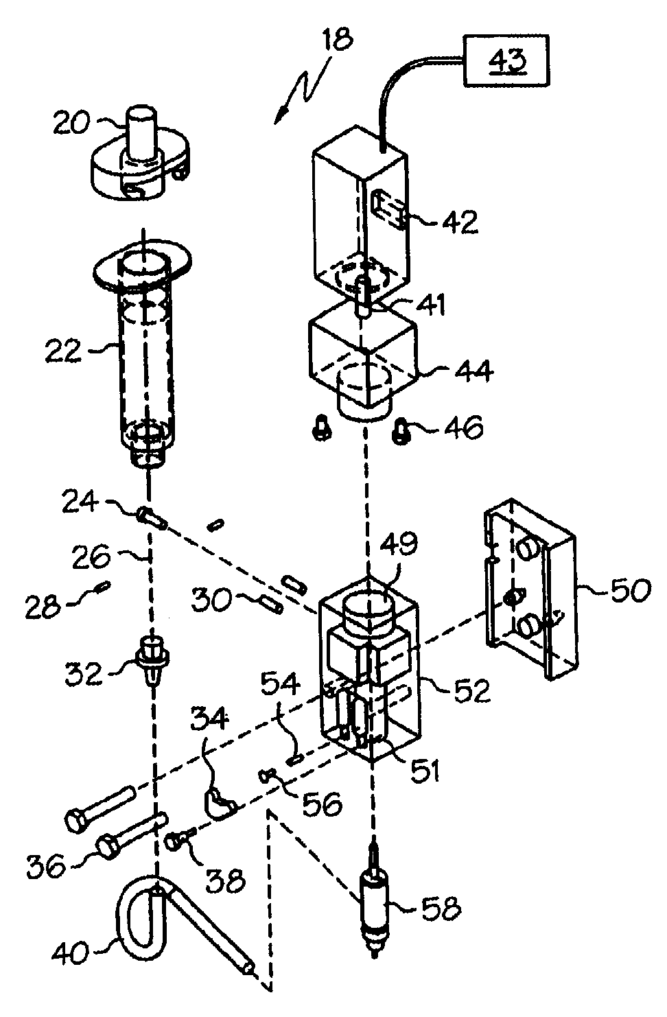
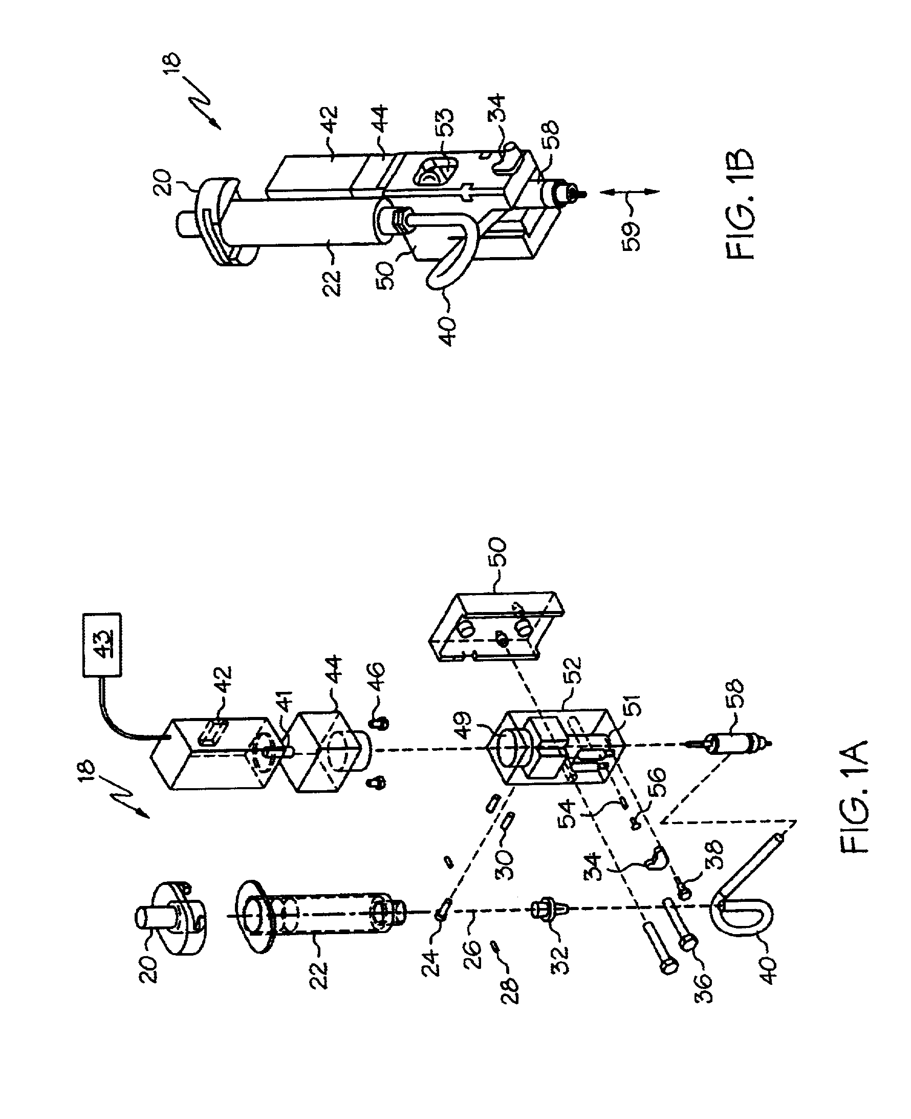
[0041]FIGS. 1A and 1B are an exploded perspective view and an assembled perspective view respectively of a pump assembly configured in accordance with the present invention. With reference to FIGS. 1A and 1B, an embodiment of the dispensing pump 18 comprises a motor 42, an optional transmission box 44, a pump housing 52, and a cartridge 58.

[0042]The motor 42 preferably comprises a closed-loop servo motor with an independent motion controller 43. The motion controller 43 may be provided by the host dispensing platform, and may comprise, for example, a Delta Tau controller, Northbridge, Calif., USA. The closed-loop servo motor may comprise, for example, a Sigma Mini Series motor, produced by Yaskawa Electric Corp., Japan. Feedback is preferably provided by a rotary encoder, for example providing 8192 discrete counts over 360 degree rotation. The motor 42 includes an axle 41 which operates to drive the feed screw in the cartridge assembly 58 (described below). In this manner, high-perf...


PUM


Abstract

In a fluid pump and cartridge assembly, a cartridge includes a material inlet port, a material outlet port, and a feed screw. The feed screw delivers fluid to be dispensed from the fluid inlet to the outlet port. The fluid inlet is preferably elongated in a direction along a longitudinal axis of the feed screw to enhance consistency in material flow through the cartridge. The feed screw is preferably driven by a closed-loop servo motor to achieve high-performance dispensing resolution. The assembly is preferably compatible with fixed-z and floating-z cartridges. A optional vented dispense tip, in combination with the fluid pump, allows for repeatable deposit of fillet patterns while maintaining optimal consistency.

Description

RELATED APPLICATIONS[0001]This application is a Continuation-in-Part of U.S. patent application Ser. No. 09 / 702,522, filed Oct. 31, 2000, which claims the benefit of U.S. Provisional Application No. 60 / 186,763, filed Mar. 3, 2000 and U.S. Provisional Application No. 60 / 163,952, filed Nov. 8, 1999 the contents of which are incorporated herein by reference, in their entirety.[0002]This application is also a Continuation-in-Part of U.S. patent application Ser. No. 09 / 491,615, filed Jan. 26, 2000, which claims the benefit of U.S. Provisional Application No. 60 / 117,201, filed Jan. 26, 1999, and U.S. Provisional Application No. 60 / 163,938, filed Nov. 8, 1999 the contents of which are incorporated herein by reference, in their entirety.[0003]This application also claims the benefit of U.S. Provisional Application No. 60 / 259,730, filed Jan. 4, 2001, the contents of which are incorporated herein by reference, in their entirety.BACKGROUND OF THE INVENTION[0004]Contemporary fluid dispense syst...

Claims


Application Information

Patent Timeline
IPC IPC(8): A62C31/00A62C31/02B05B1/14B05B1/00B05C5/02B05C11/10B05C17/00B05C17/005
CPCB05C5/0225B05C11/1034B05C17/00579B05C17/002
Inventor FUGERE, JEFFREY P.
Owner DL TECH
Why Eureka
Try Eureka