Internal cooling circuit for gas turbine bucket

a technology of internal cooling circuit and gas turbine, which is applied in the direction of liquid fuel engines, marine propulsion, vessel construction, etc., can solve the problems of unattractive cooling air, achieve the effects of improving heat transfer, and improving overall turbine cycle efficiency

Inactive Publication Date: 2005-10-25
GENERAL ELECTRIC CO
View PDF4 Cites 46 Cited by
  • Summary
  • Abstract
  • Description
  • Claims
  • Application Information

AI Technical Summary

Benefits of technology

[0009]Advantages of the closed circuit serpentine design, with turbulators and tip turn guide vanes, include improved heat transfer from the buckets to the steam by using a high capacity cooling medium, i.e., the steam, as well as improved overall turbine cycle efficiency over conventional air cooled buckets since steam is extracted from the top cycle of the steam turbine, used to cool the bucket and is then returned to the bottom cycle of the steam turbine in a closed loop. This results in improved overall turbine cycle efficiency over conventional arrangements where compressor discharge air is used for cooling, and then discharged into the hot gas path.

Problems solved by technology

For the high gas path temperatures expected in advanced gas turbine engines, cooling air is not attractive due to the high cycle efficiency penalties associated with using compressor discharge air.

Method used


Image

  • Internal cooling circuit for gas turbine bucket
  • Internal cooling circuit for gas turbine bucket
  • Internal cooling circuit for gas turbine bucket

Examples


Embodiment Construction

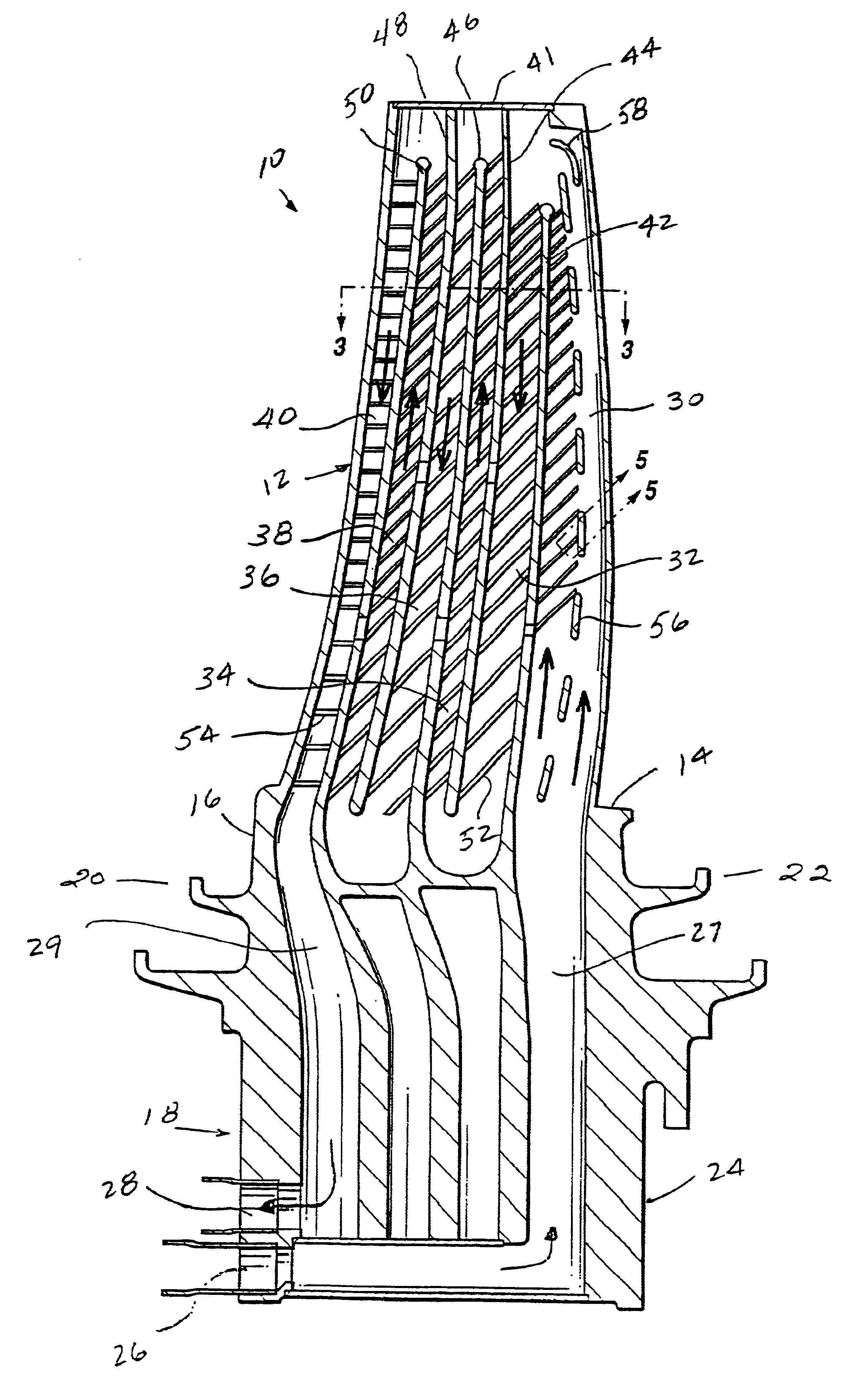
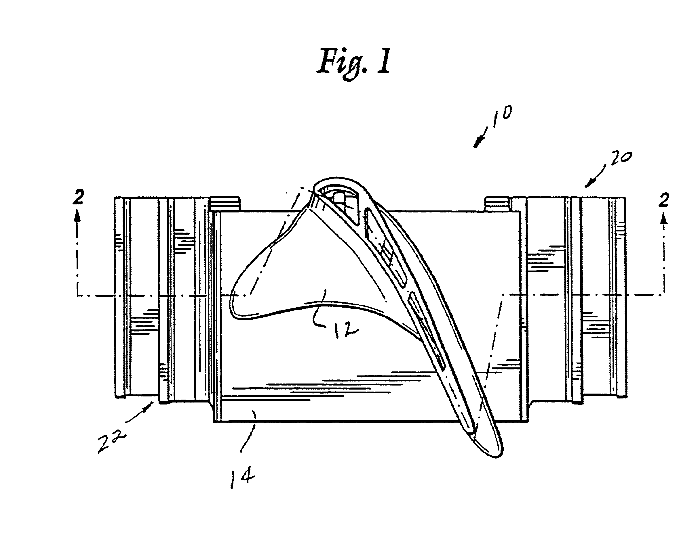
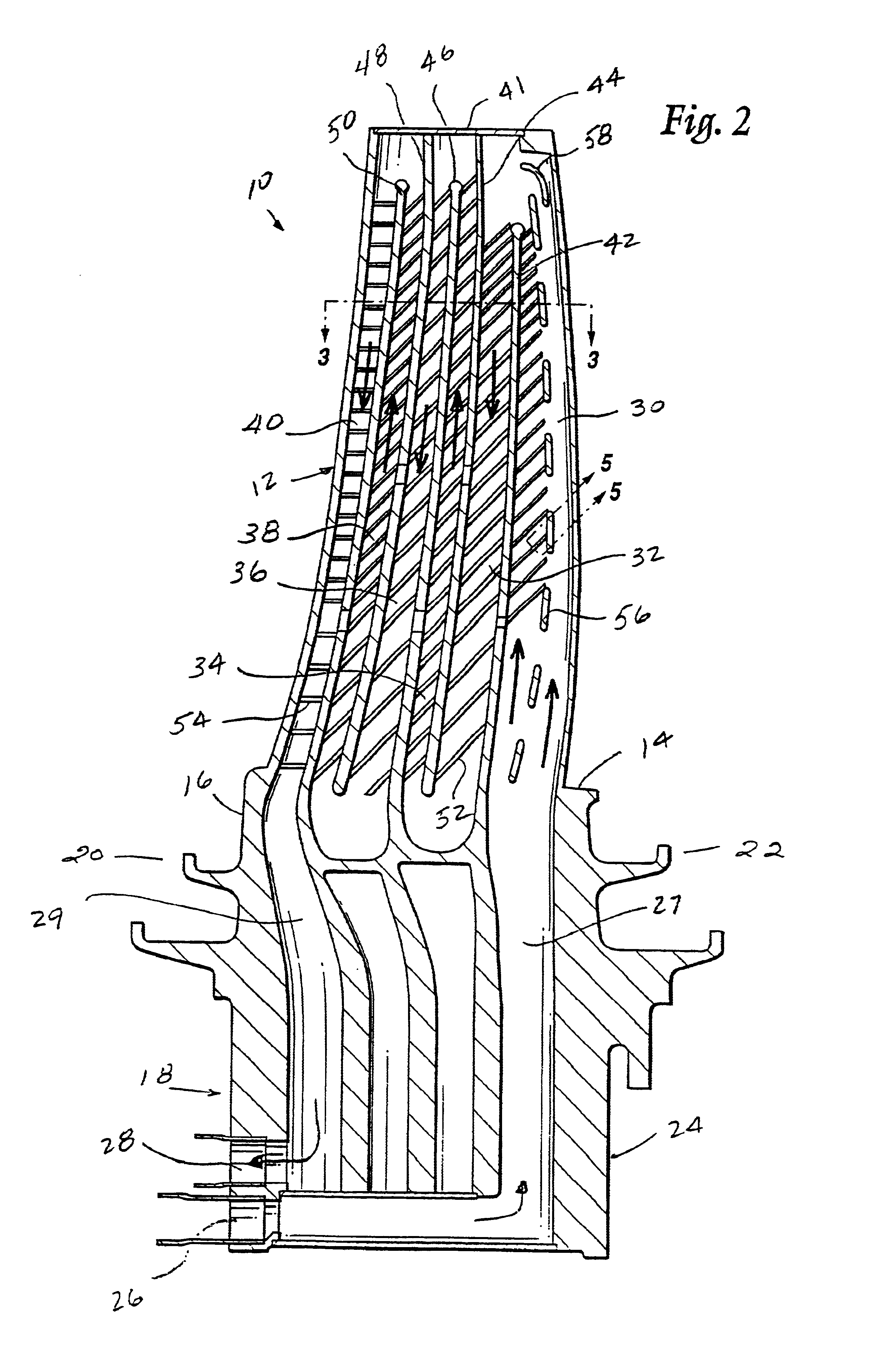
[0016]Referring to FIGS. 1 and 2, a second stage bucket 10 in accordance with this invention includes an airfoil portion 12 attached to a platform portion 14 which seals the shank 16 of the bucket from the hot gases in the combustion flow path. The shank 16 is attached to a rotor disk by a conventional dovetail 18. Angel wing seals 20, 22 provide sealing of the wheel space cavities. With reference also to FIG. 6, the dovetail 18 includes an extension 24 below the dovetail which serves to supply and remove cooling steam from the bucket via axially arranged passages 26 and 28 which communicate with axially oriented rotor passages (not shown). The airfoil portion 12 has leading and trailing edges 13, 15, respectively, and pressure and suction sides 17, 19, respectively.

[0017]With specific reference now to FIG. 2, the internal cooling passages in the second stage bucket define a closed serpentine circuit having a total of six radially extending passages 30, 32, 34, 36, 38 and 40, with a...


PUM


Abstract

In a gas turbine bucket having a shank portion and an airfoil portion having leading and trailing edges and pressure and suction sides, an internal cooling circuit, the internal cooling circuit having a serpentine configuration including plural radial outflow passages and plural radial inflow passages, and wherein a coolant inlet passage communicates with a first of the radial outflow passages along the trailing edge, the first radial outflow passage having a plurality of radially extending and radially spaced elongated rib segments extending between and connecting the pressure and suction sides in a middle region of the first passage to prevent ballooning of the pressure and suction sides at the first radial outflow passage.

Description

[0001]This is a continuation of Ser. No. 09 / 236,714 filed Jan. 25, 1999 now abandoned.[0002]This invention was made with Government support under Contract No. DE-FC21-95MC31176 awarded by the Department of Energy. The Government has certain rights in this invention.BACKGROUND OF THE INVENTION[0003]This invention relates to an internal cooling circuit for a stage two bucket in a gas turbine.[0004]High gas path temperatures are required to achieve high output and high efficiency in gas turbine machines. Several rows (or stages) of rotating blades or buckets, made from various high temperature alloys, are used in the gas turbine to extract energy from the hot gas path. To maintain temperatures of the first and second stage buckets within the material design limits, internal cooling is required. For the high gas path temperatures expected in advanced gas turbine engines, cooling air is not attractive due to the high cycle efficiency penalties associated with using compressor discharge a...

Claims


Application Information

Patent Timeline
Patent Type & Authority Patents(United States)
IPC IPC(8): F01D5/18F02C7/16
CPCF01D5/187F01D5/18F02C7/16
Inventor HYDE, SUSAN MARIEDAVIS, RICHARD MALLORY
Owner GENERAL ELECTRIC CO
Why Eureka
Try Eureka