Ranged dual clutch transmission for motor vehicles

a dual clutch, motor vehicle technology, applied in mechanical equipment, gears, transportation and packaging, etc., can solve the problem of low number of gears and couplers for the number of gear ratios produced, and achieve the effect of small torque ratio and small torque ratio

Inactive Publication Date: 2005-10-25
FORD GLOBAL TECH LLC
View PDF3 Cites 90 Cited by
  • Summary
  • Abstract
  • Description
  • Claims
  • Application Information

AI Technical Summary

Benefits of technology

[0009]This invention provides multiple forward gear ratios, yet it has a small number of gears and couplers because a range coupler selects between high and low range output ratios. One of the forward gear torque paths avoids transmitting torque through a range select coupler. While operating in that gear and without interrupting power flow between the engine and the transmission input, the state of the range coupler is changed to the high range in preparation for an upshift, and to the low range in preparation for a downshift. Furthermore, this transmission uses some of the pinion-gear meshes to produce multiple gear ratios, resulting in a low number of gears and couplers for the number of gear ratios produced. An additional advantage of this invention is the small torque ratio step between the gear ratio in which the vehicle is launched and the next higher gear ratio and the small torque ratio steps between other gear ratios.
[0010]Gear ratio changes are accomplished through the use of couplers, such as synchronizers or dog clutches, which mutually driveably connect components operative in each speed ratio. The couplers produce very little drag loss when engaged, and do not require a continuous supply of power to stay engaged.

Problems solved by technology

Furthermore, this transmission uses some of the pinion-gear meshes to produce multiple gear ratios, resulting in a low number of gears and couplers for the number of gear ratios produced.

Method used


Image

  • Ranged dual clutch transmission for motor vehicles
  • Ranged dual clutch transmission for motor vehicles
  • Ranged dual clutch transmission for motor vehicles

Examples


Embodiment Construction

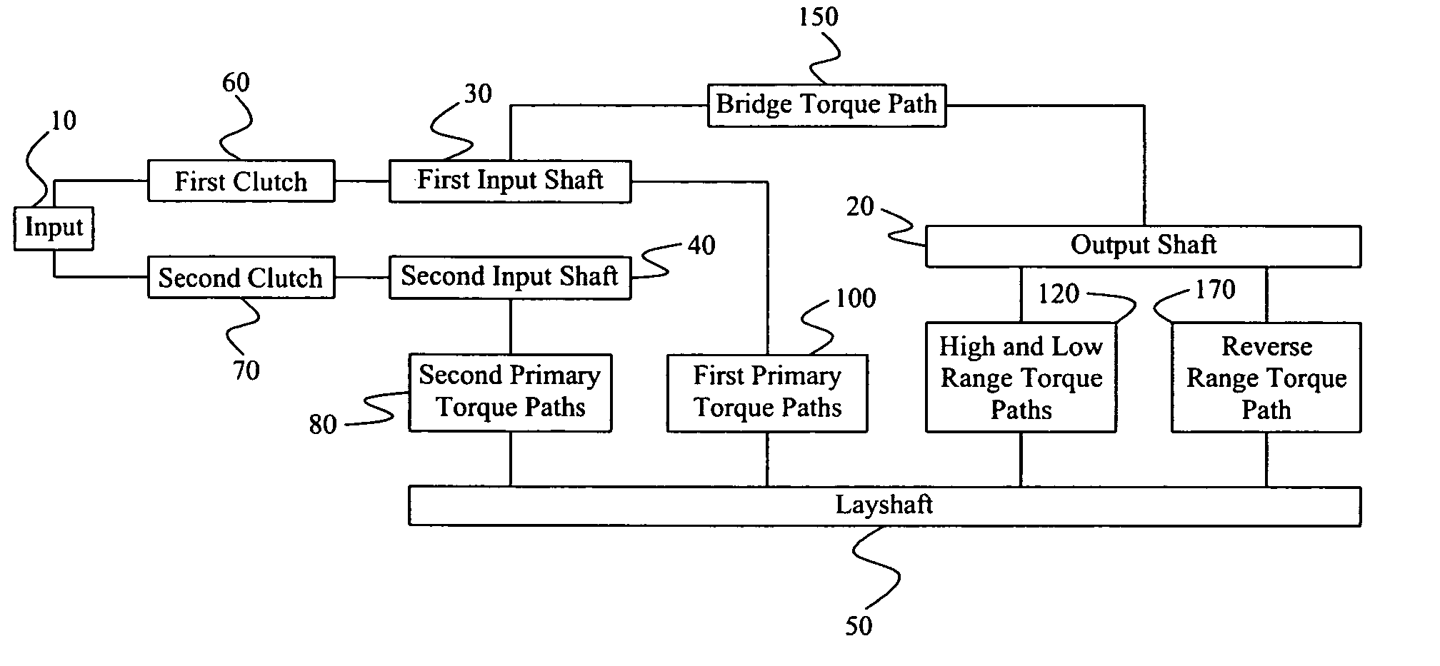
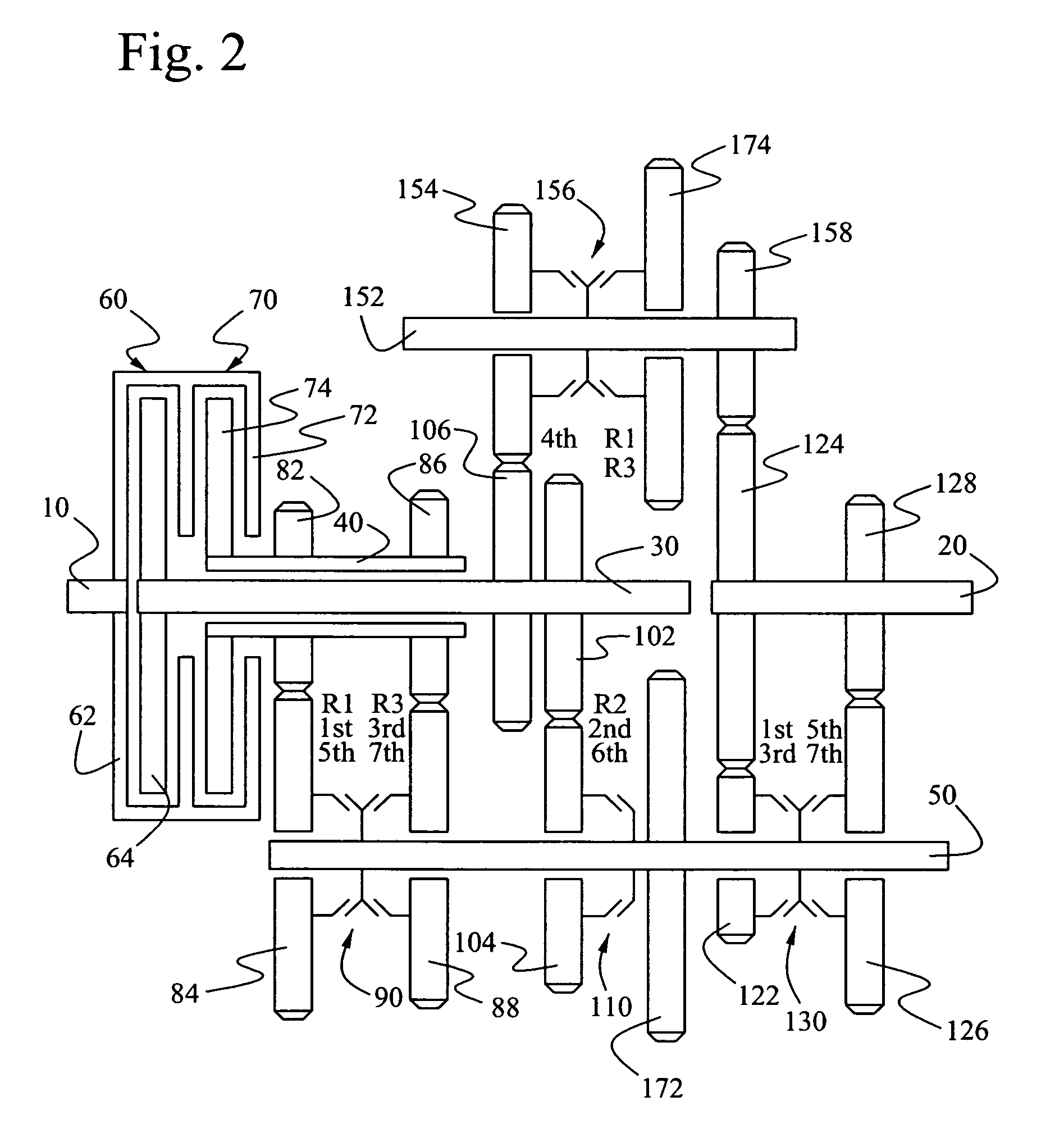
[0020]Referring now to FIGS. 1, 2, and 5, a transmission according to the present invention includes an input 10 for driveably connecting a power source such as an internal combustion engine or electric motor to the transmission, and an output 20 for driving a load, such as the driven wheels of a motor vehicle, through a powertrain that may include a drive shaft, differential mechanism, and axle shafts.

[0021]A first friction clutch 60, consisting of a clutch housing 62 and a clutch disk 64, alternately connects and disconnects a first input shaft 30 as clutch 60 is engaged and disengaged, respectively. Similarly, a second friction clutch 70, consisting of a clutch housing 72 and a clutch disk 74, alternately connects and disconnects a second input shaft 40 as clutch 70 is engaged and disengaged, respectively. Second input shaft 40 is hollow so that it can be concentric with the first input shaft 30.

[0022]A layshaft 50 is arranged substantially parallel to the axis of the input 10 an...


PUM


Abstract

A power transmission for a motor vehicle includes an input, first and second input shafts, a layshaft, drive elements connecting the input shafts to the output and layshaft, couplers, a first clutch for connecting and disconnecting the input and the first input shaft, and a second clutch for connecting and disconnecting the input and the second input shaft. A first torque path driveably connects the first input shaft to the layshaft. A second torque path driveably connects the second input shaft to the layshaft. A third torque path driveably connects the layshaft and output. A bridge torque path driveably connects the first input shaft and the output.

Description

BACKGROUND OF THE INVENTION[0001]1. Field of the Invention[0002]This invention relates to auto transmissions having a layshaft kinematic arrangement, particularly to such transmissions having input clutches but no torque converter.[0003]2. Description of the Prior Art[0004]Automatic transmissions for transmitting power between an input and an output, either over a continuously variable range of speed ratios or in discrete step changes among speed ratios, have associated with them several sources of parasitic losses, which adversely affect fuel economy. These losses are associated with a torque converter, open friction clutches and brakes, hydraulic pump, and gear meshes.[0005]To improve fuel economy in a motor vehicle having an automatic transmission, an automated shift manual (ASM) transmission can be used to eliminate or substantially reduce all of these parasitic losses except gear mesh losses. An ASM transmission generally performs gear ratio changes by first interrupting torque...

Claims


Application Information

Patent Timeline
Patent Type & Authority Patents(United States)
IPC IPC(8): F16H3/08F16H3/00F16H37/02F16H3/091F16H3/097F16H3/093F16H37/04
CPCF16H3/006F16H3/093F16H37/042F16H3/097Y10T74/19233F16H2200/006F16H2200/0091Y10T74/19219F16H2200/0056
Inventor JANSON, DAVIDBALDWIN, REIDHOFFMAN, DONALD E.
Owner FORD GLOBAL TECH LLC
Why Eureka
Try Eureka