Retractable needle syringe including a sheath and an intravenous adapter

a syringe and hypodermic technology, applied in the field of syringe sheaths for hypodermic syringes, can solve the problems of inability to contemplate changing needles after filling the syringe, injection fluid may be present on the outside of the needle, and the risk of drawing in fragments or slivers of material is not practical, so as to avoid any risk of compromising the needle proper and reduce the risk of needle stick injuries

Inactive Publication Date: 2005-10-25
NMT GRP PLC
View PDF184 Cites 109 Cited by
  • Summary
  • Abstract
  • Description
  • Claims
  • Application Information

AI Technical Summary

Benefits of technology

[0010]The sheath may be shaped or adapted so as to be capable of penetrating the rubber cap of a vial or the like. To this end, it may be provided with a pointed end or a separate needle. In this way, the sheath may be used as a needle during filling of the syringe thereby avoiding any risk of compromising the needle proper as discussed above through having to use the needle proper to pierce a rubber cap for instance.
[0011]When used with a syringe having needle retraction means, the needle need only be exposed during the time that it is actually in use for the administration of an injection. At all other times, including filling of the syringe, the needle may be effectively inaccessible thereby considerably reducing the risk of needle stick injuries since the sheath need not be particularly sharp as it is only used for filling the syringe.

Problems solved by technology

In the case of syringes with provision for retraction of the needle after use as disclosed for instance in our prior U.S. Pat. No. 5,782,804, the needle assembly tends to be specially designed for this purpose and it is not therefore practical to contemplate changing needles after filling the syringe and before administering the injection.
There are also concerns over the risks of drawing in fragments or slivers of material, e.g. glass, when the syringe is filled from for example an ampoule following breaking of a glass or other cap of the ampoule.
Moreover, if the same needle is used to fill the syringe and also administer the medication, some injection fluid may be present on the outside of the needle which may be undesirable since some substances for injection can be irritating to the skin.

Method used


Image

  • Retractable needle syringe including a sheath and an intravenous adapter
  • Retractable needle syringe including a sheath and an intravenous adapter
  • Retractable needle syringe including a sheath and an intravenous adapter

Examples


Embodiment Construction

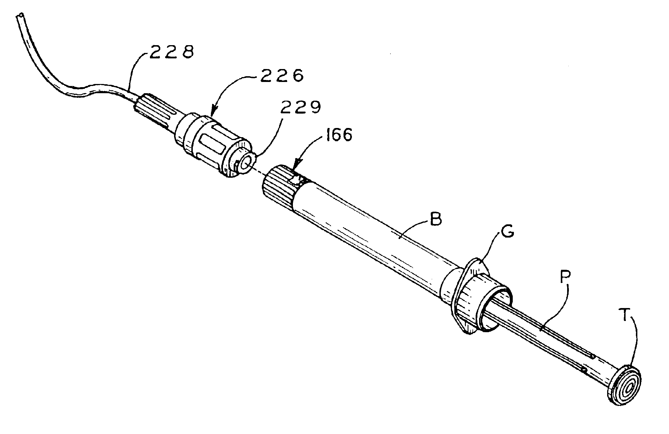
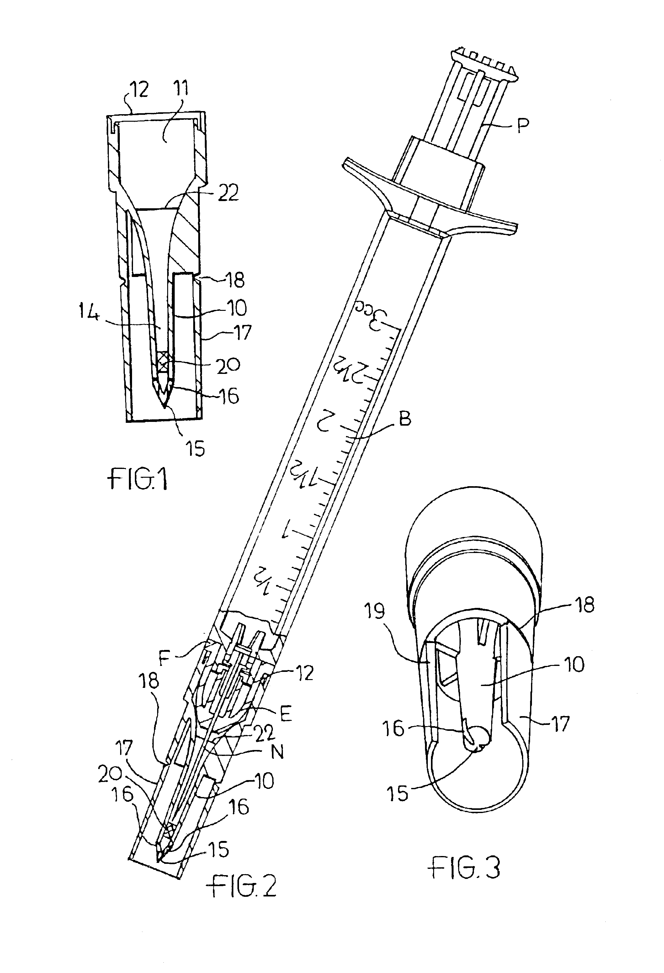
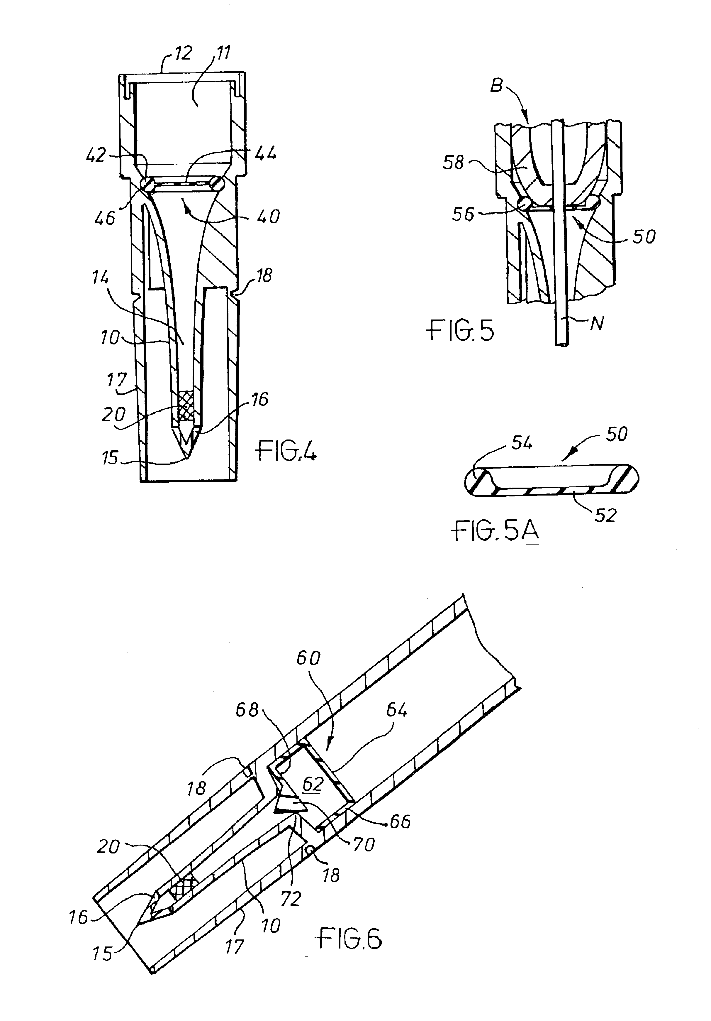
[0050]Referring now to FIGS. 1 to 3 of the drawings, the sheath 10 is formed, e.g. from metal or a plastics material, with a socket 11 at its rear end for engagement with the end cap E of a hypodermic syringe having a needle N, barrel B and plunger P. The sheath may engage with the syringe with push-on / pull-off friction fit. An annular seal 12 is provided on the end of the sheath 10 which abuts the forward face of an annular flange F at the rearward end of the cap E.

[0051]The sheath 10 has a hollow interior 14 which accommodates the needle N of the syringe. The sheath 10 terminates in a pointed forward end 15 capable of penetrating the rubber cap of a vial or being inserted into an ampoule whose cap has been broken therefrom. The sheath is apertured at a location in close proximity to the pointed end 15, the aperture being formed by an axially extending elongate slot. In the illustrated embodiment, two such slotted apertures 16 are provided on diametrically opposite sides of the she...


PUM


Abstract

A syringe assembly including an adapter, a sheath and filling spike for connecting to said adapter and an intravenous connector for intravenously administering medicine to a patient. The barrel may be connected to the adapter and the filling spike for filling the barrel with medicine. The medicine can then be injected into a patient through either the needleless intravenous injection system or through a retractable needle assembly.

Description

[0001]This is a continuation-in-part of U.S. patent application Ser. No. 09 / 563,268 entitled “Needle Sheath”, filed May 3, 2000 now U.S. Pat. No. 6,524,278, which is a continuation of PCT / GB99 / 02175, filed Jul. 7, 1999.BACKGROUND OF THE INVENTION[0002]This invention concerns a sheath for the needle of a hypodermic syringe.[0003]Hypodermic syringe assemblies are usually provided with a protective sheath covering the needle for its protection until the syringe is required for use.[0004]It is a common, though by no means universal, practice to change the needle of a syringe after filling and before administration of the injection because of a perception that the original needle may become blunted, bent or subjected to loss of needle lubricant during the filling operation, for example by insertion through the rubber cap of the vial, contaminated with a foreign substance, for example latex from such a cap or rendered unsterile, or to suit filling requirements for rapid filling of the syr...

Claims


Application Information

Patent Timeline
Patent Type & Authority Patents(United States)
IPC IPC(8): A61J1/00A61M5/32A61M39/02A61M39/04A61M5/178A61M5/31A61M5/50A61J1/20
CPCA61J1/2096A61M5/3202A61M5/3234A61J2001/201A61J2001/2013A61J2001/2086A61M5/1782A61M5/3145A61M5/32A61M5/329A61M5/508A61M2005/3118A61M2005/3128A61M2005/3201A61M2039/042A61J1/201A61J1/2013A61J1/2086
Inventor DONNAN, JEREMY FRANCISTARGELL, DAVID JOHN
Owner NMT GRP PLC
Why Eureka
Try Eureka