Computed tomography apparatus

a tomography and computed tomography technology, applied in tomography, patient positioning for diagnostics, instruments, etc., can solve the problem that the computed tomography apparatus cannot be used for examination, and achieve the effect of simple technology

Inactive Publication Date: 2005-10-25
SIEMENS HEALTHCARE GMBH
View PDF14 Cites 68 Cited by
  • Summary
  • Abstract
  • Description
  • Claims
  • Application Information

AI Technical Summary

Benefits of technology

[0008]An object of the present invention is to provide a computed tomography apparatus of the type described above which allows a technically simple way for preparing patients on the support table for examinations without blocking the computed tomography apparatus.

Problems solved by technology

During that time, the computed tomography apparatus cannot be used for examinations, since the service personnel are occupied with waiting while the patient climbs onto the support table, which is firmly attached to the computed tomography apparatus and which is technically complicated, and the service personnel are then occupied with positioning the patient thereon.

Method used


Image

  • Computed tomography apparatus
  • Computed tomography apparatus
  • Computed tomography apparatus

Examples


Embodiment Construction

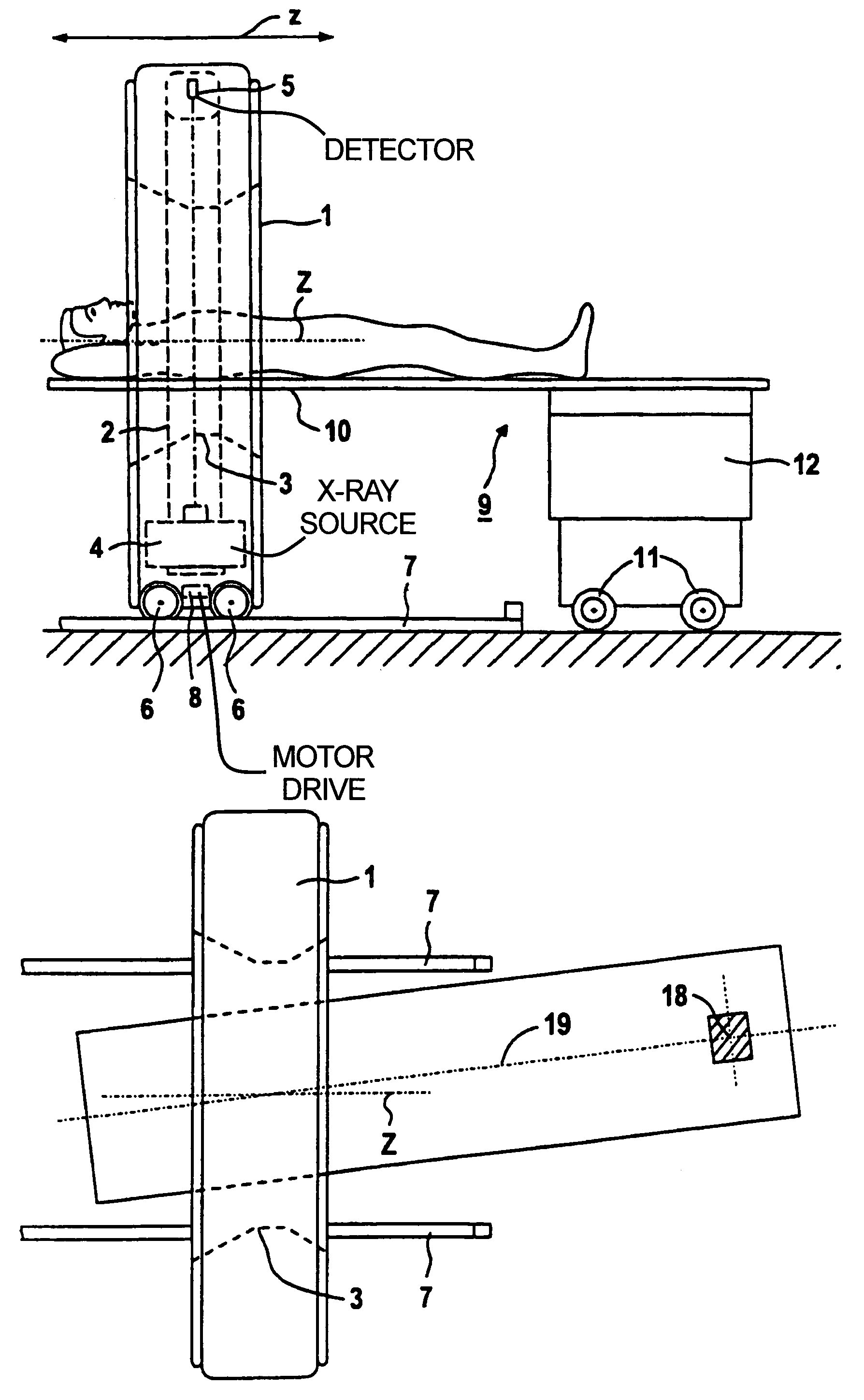
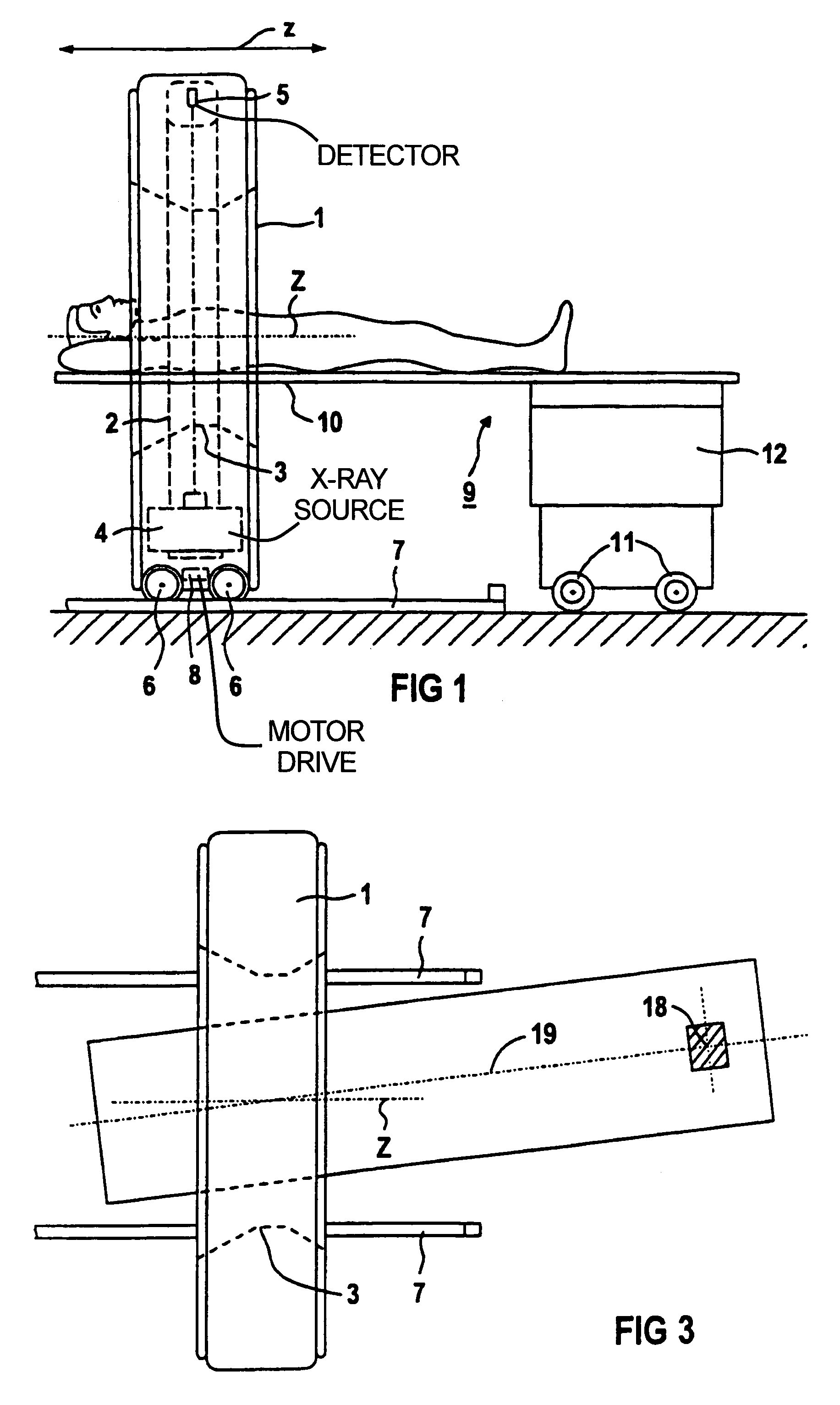
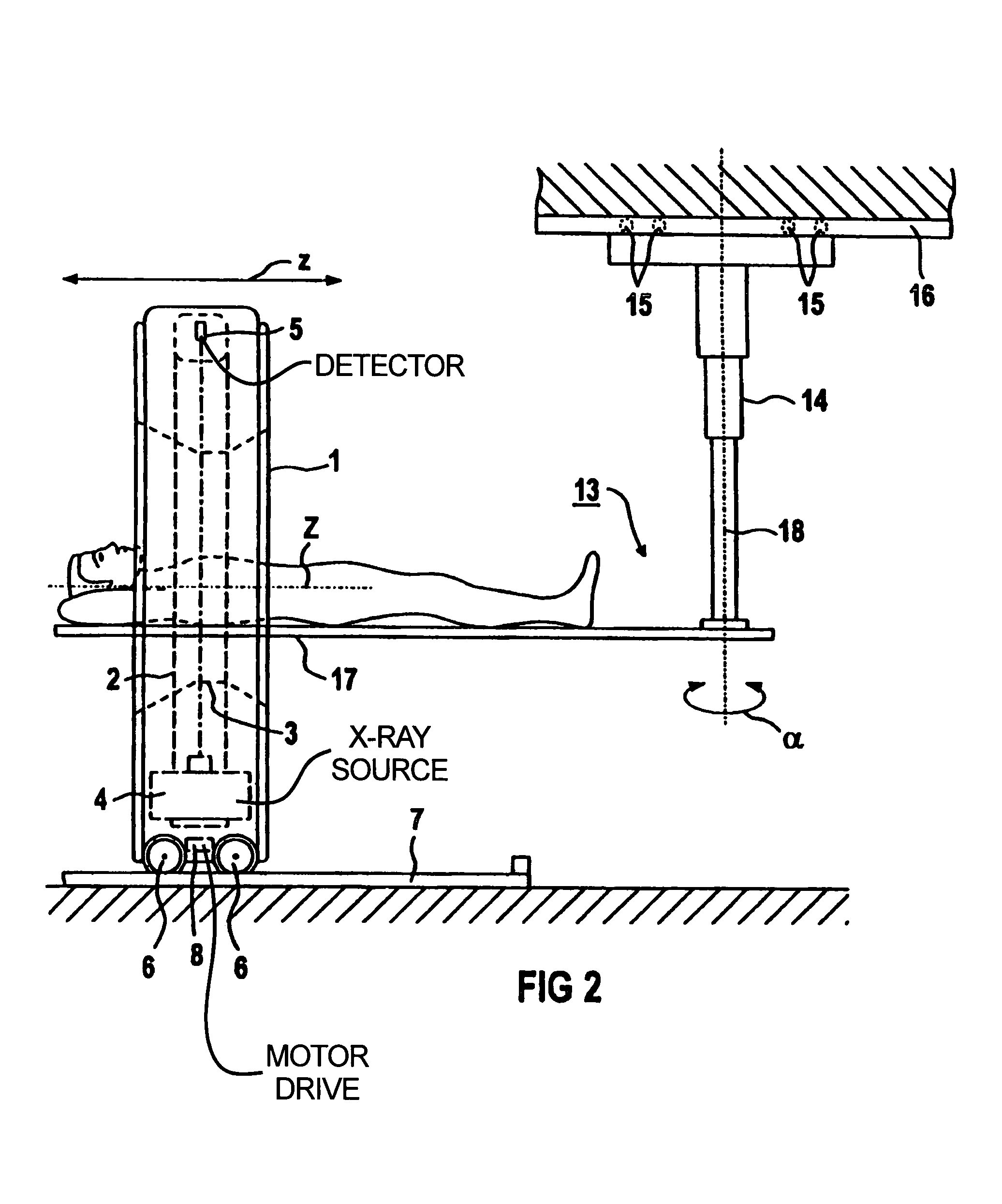
[0017]FIG. 1 shows a computed tomography apparatus having a gantry 1 with a measuring opening 2, which is surrounded by a rotary ring 3 on which an x-ray source 4 and a curved detector 5 are mounted. The x-ray source 4 emits a fan-shaped x-ray bundle (not shown) that is incident on the detector 5, which is curved around the focus of the x-ray source 4 and which is formed by a series of individual detectors.

[0018]By means of rollers 6 on parallel rails (only one is visible in FIG. 1), the gantry 1 is movable in the direction of the double arrow z by a motor drive 8 (shown in broken lines in FIG. 1). This movement is independent of a support table 9 on which a support plate 10 for a patient to be examined is situated.

[0019]For producing computed tomographic images, the gantry 1 with the x-ray source 4 and the detector 5 is moved from a standby position (not shown) relative to the support table 9, into a use position in which the support plate 10 of the support table 9 extends through ...


PUM

PropertyMeasurementUnit
computed tomographyaaaaaaaaaa
lengthaaaaaaaaaa
volumeaaaaaaaaaa

Abstract

A computed tomography apparatus has a gantry with a measuring opening, with an x-ray source movable around the measuring opening for irradiating an examination area from different directions, a detector for registering corresponding sets of projection data, and at least one support table having a support plate. The gantry can be moved into a use position independently of the support table and the support table is fashioned such that the support plate extends through the measuring opening when the gantry assumes a use position.

Description

BACKGROUND OF THE INVENTION[0001]1. Field of the Invention[0002]The present invention is directed to a computed tomography apparatus of the type having a gantry with a measuring opening, an X-ray source movable around the measuring opening for irradiating an examination area from different directions, a detector for registering corresponding projections, and at least one support table having a support plate, with the gantry being movably fashioned such that it can be moved into at least one use position.[0003]2. Description of the Prior Art[0004]U.S. Pat. No. 5,448,607 and U.S. Pat. No. 5,499,415 describe computed tomography apparatuses of the above general type.[0005]It has been determined that approximately 50 through 60% of the time spent at computed tomography apparatuses in hospitals at the moment is occupied by positioning the patient on the support table in a way appropriate for the respective examination. During that time, the computed tomography apparatus cannot be used for...

Claims


Application Information

Patent Timeline
Patent Type & Authority Patents(United States)
IPC IPC(8): A61B6/03A61B6/04
CPCA61B6/032A61B6/04
Inventor SOMMER, ANDRES
Owner SIEMENS HEALTHCARE GMBH
Why Eureka
Try Eureka