Plate type heat exchanger and method of manufacturing the heat exchanger

a heat exchanger and plate technology, applied in the field of plate heat exchangers, can solve the problems of increasing the size reducing the service life of the heat exchanger, so as to achieve reliable plate heat exchangers, enhance the degree of contact between the plates, and enhance the yield

Inactive Publication Date: 2005-11-01
CONSOL SYST +1
View PDF23 Cites 64 Cited by
  • Summary
  • Abstract
  • Description
  • Claims
  • Application Information

AI Technical Summary

Benefits of technology

[0030]According to this method, when the plates are piled up, contact of burrs formed thereon during pressing is avoided and, hence, the degree of contact between the plates is enhanced. Accordingly, the plates are positively joined together by plating and subsequent brazing, making it possible to enhance the yield and provide reliable plate heat exchangers.
[0031]Alternatively, the step of performing plating may be replaced by the step of coating with paste solder those surfaces of the plurality of plates that are positioned on an upstream side thereof in a punching direction during pressing. The use of the paste solder that is cheaper than plating reduces the manufacturing cost of the plate heat exchangers. Also, because the solder is coated on the upstream side surfaces of the plates with respect to the punching direction during pressing, i.e., on the surfaces of the plates on which no burrs project, jigs or tools such as masks to be used during coating are not appreciably damaged by the burrs, thus enhancing the reliability of the plate heat exchangers.

Problems solved by technology

Although they can be taken apart and cleaned, they have the disadvantage of being limited in the range of temperature or pressure of the fluids to be used.
Because the heat exchange fluids A, B form cross- or rectangular-current flows that are in a heat exchange relationship, and because the cross- or rectangular-current flows are inferior in heat transfer efficiency to countercurrent flows, the conventional plate heat exchanger referred to above requires a heat transfer area greater than that required by a heat exchanger of the countercurrent flow type to obtain a predetermined heat transfer capacity, resulting in an increase in size of the heat exchanger.
Because the plates are joined together by virtue of diffusion of the material in the vicinity of the mating surfaces of the plates, a considerably large load is required for the application of pressure during joining, thus requiring relatively large pressure equipment.
Accordingly, it is difficult to mass-produce the plate heat exchangers at a low cost.
Because the joining by bonding is poor in pressure resistance or heat resistance of the bonded portions, the use pressure or temperature of the heat exchangers is considerably limited.
However, if the degree of contact between the neighboring plates during brazing is bad, a gap or gaps are created in the brazed portions of the plates, thus causing leakage of the heat exchange fluids.
When the plates are piled up, contact of such burrs considerably deteriorates the degree of contact between the neighboring plates, resulting in poor brazing.

Method used


Image

  • Plate type heat exchanger and method of manufacturing the heat exchanger
  • Plate type heat exchanger and method of manufacturing the heat exchanger
  • Plate type heat exchanger and method of manufacturing the heat exchanger

Examples


embodiment 1

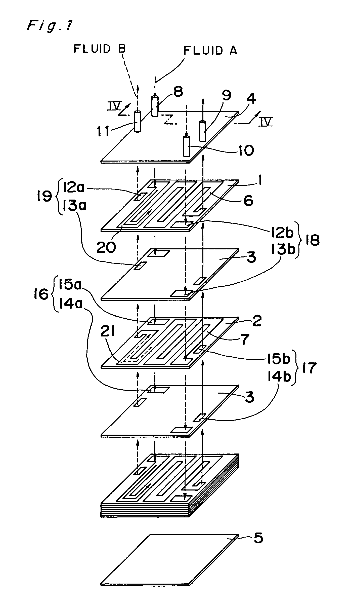
[0041]FIG. 1 depicts a plate heat exchanger according to a first embodiment of the present invention, with a portion thereof taken apart for ease of understanding of the interior structure thereof.

[0042]This plate heat exchanger includes a plurality of plates sandwiched between a pair of end plates extending parallel to each other, with a plurality of separate passageways defined in some of the plates. The plurality of passageways are not in fluid communication with each other and are defined in different plates. The directions of flow of fluids in the plurality of passageways are essentially opposite to each other.

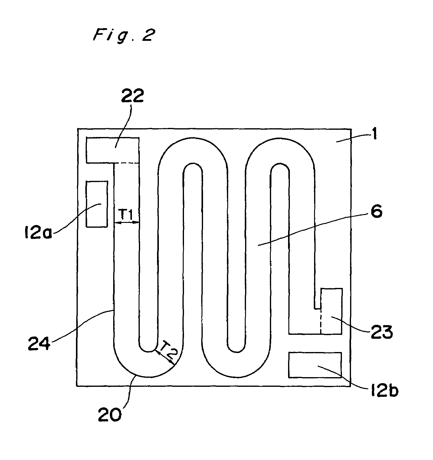
[0043]More specifically, as shown in FIG. 1, a plurality (first group) of passageway plates 1 each having a passageway 6 defined therein as a penetration for the passage of a heat exchange fluid A and a plurality (second group) of passageway plates 2 each having a passageway 7 defined therein as a penetration for the passage of a heat exchange fluid B are piled up (stacke...

embodiment 2

[0060]FIG. 3 depicts a plate heat exchanger according to a second embodiment of the present invention:

[0061]This plate heat exchanger includes a plurality of plates sandwiched between a pair of end plates and each having a plurality of separate passageways defined therein as penetrations that are not in fluid communication with each other. The directions of flow of fluids in the plurality of passageways are essentially opposite to each other.

[0062]More specifically, as shown in FIG. 3, a plurality of passageway plates 31 each having passageways 34, 35 defined therein as penetrations are piled up (stacked) one upon the other and sandwiched between a pair of end plates 32, 33. The passageways 34, 35 adjoin and extend parallel to each other to form respective boustrophedonic fluid paths. The directions of flow of the heat exchange fluid A in the passageways 34 and the heat exchange fluid B in the passageways 35 are countercurrent (opposite) with respect to each other.

[0063]Each passage...

embodiment 3

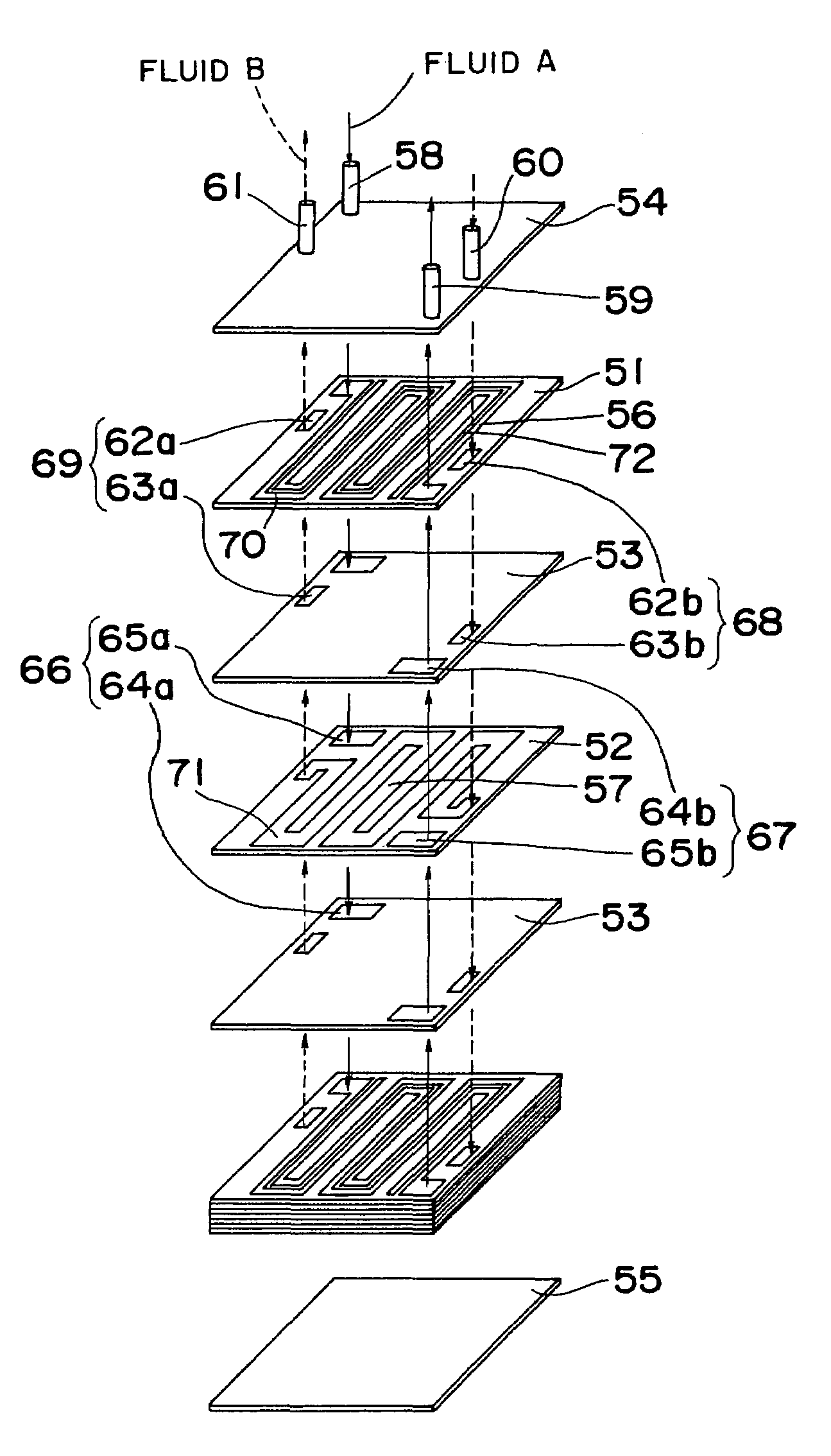
[0070]FIG. 4 depicts a plate heat exchanger according to a third embodiment of the present invention.

[0071]This plate heat exchanger includes a plurality (first group) of passageway plates 51 each having a passageway 56 defined therein as a penetration for the passage of a heat exchange fluid A, and a plurality (second group) of passageway plates 52 each having a passageway 57 defined therein as a penetration for the passage of a heat exchange fluid B. These passageway plates 51, 52 are piled up (stacked) alternately and sandwiched between a pair of end plates 54, 55, with a partition plate 53 interposed between adjacent passageway plates 51, 52. The passageway 56 in each passageway plate 51 is divided into two sections in the widthwise direction thereof by a partition member 72.

[0072]Each passageway plate 51 has through-holes 62a, 62b defined therein in addition to the passageway 56, while each passageway plate 52 similarly has through-holes 65a, 65b defined therein in addition to ...


PUM

PropertyMeasurementUnit
thicknessaaaaaaaaaa
surface area per volumeaaaaaaaaaa
temperatureaaaaaaaaaa

Abstract

A plate heat exchanger includes a plurality of plates sandwiched between a pair of end plates. Each of the plurality of plates has two passageways defined therein that are not in fluid communication with each other. Alternatively, some of the plurality of plates have a passageway, while some of the remaining plates have another passageway. Two fluids flow through the two passageways in a countercurrent fashion. Because the countercurrent flows are superior in heat transfer efficiency, it is possible to enhance the performance and reduce the size of the plate heat exchangers.

Description

TECHNICAL FIELD[0001]The present invention relates to plate heat exchangers employing, as heat exchange fluids, a liquid and a two-phase fluid undergoing a phase change in vapor and liquid phases to exchange heat between the liquid and two-phase fluid.BACKGROUND ART[0002]The plate heat exchangers generally include a stack of metal plates having separated passageways defined therein through which heat exchange fluids flow to exchange heat therebetween. The plate heat exchangers have a large surface area per volume and can be made compact. Because they can be made with a lesser amount of material, they gradually surpass tube and shell heat exchangers in use. In ordinary plate heat exchangers, outer peripheral portions of the plates or header holes are sealed with gaskets, and the plates are mechanically fixed. Although they can be taken apart and cleaned, they have the disadvantage of being limited in the range of temperature or pressure of the fluids to be used.[0003]Japanese Laid-Op...

Claims


Application Information

Patent Timeline
Patent Type & Authority Patents(United States)
IPC IPC(8): F28D9/00B21D53/04F28F3/00F28F3/04F28F13/14
CPCF28D9/0075F28F3/04Y10T29/49366Y10T29/49393F28F2250/102F28D9/00
Inventor MATSUMOTO, SATOSHIWATANABE, TAKESHINISHIYAMA, YOSHITSUGU
Owner CONSOL SYST
Why Eureka
Try Eureka