Engine balancer with chain drive vibration isolation

a technology of vibration isolation and balancer, which is applied in the direction of machines/engines, mechanical equipment, hoisting equipment, etc., can solve the problem of not providing much further reduction of the radiated chain whine noise transmitted from the engine, and achieve the effect of reducing the audible transmitted chain whine nois

Inactive Publication Date: 2005-11-01
GM GLOBAL TECH OPERATIONS LLC
View PDF8 Cites 10 Cited by
  • Summary
  • Abstract
  • Description
  • Claims
  • Application Information

AI Technical Summary

Benefits of technology

[0005]The present invention provides an engine balancer with a compliant or elastomeric isolator ring mounted in at least one of the balancer drive sprockets to decouple chain whine vibration from the associated balance shaft. The isolator ring in the sprocket substantially reduces the audible transmitted chain whine noise from the engine structure. The invention utilizes a splined isolator ring which is placed between internal and external splines form...

Problems solved by technology

Application of an additional isolator ring to the drive sprocket of the second balance shaft, which is driven in part throug...

Method used


Image

  • Engine balancer with chain drive vibration isolation
  • Engine balancer with chain drive vibration isolation
  • Engine balancer with chain drive vibration isolation

Examples


Embodiment Construction

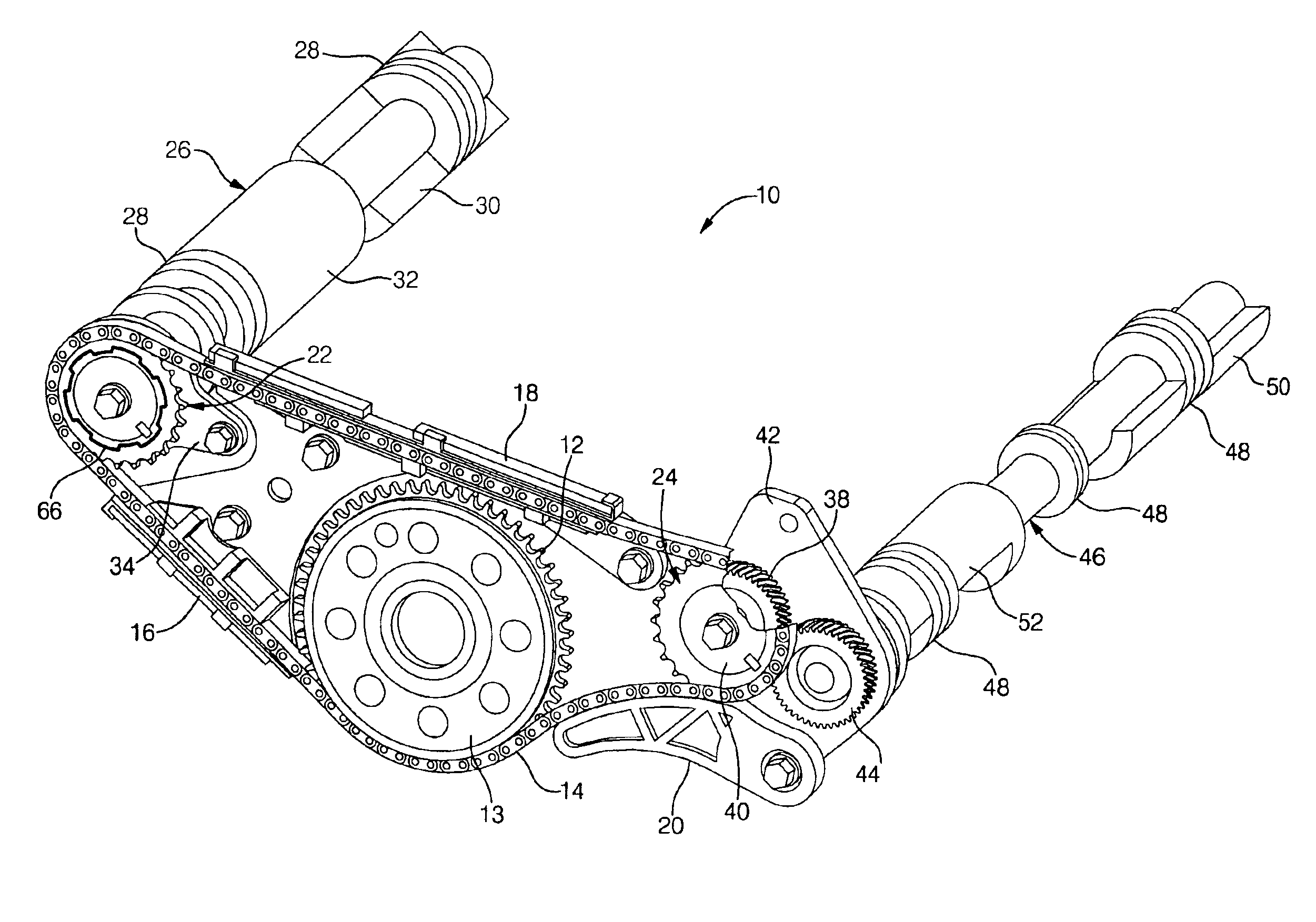
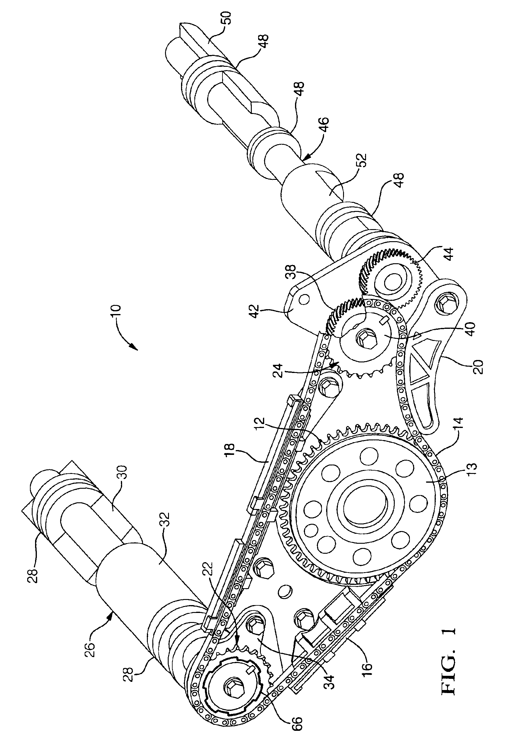
[0011]Referring first to FIG. 1 of the drawings in detail, numeral 10 generally indicates a first embodiment of an engine balancer for application to an engine having a second order pitching couple but exemplary, in general, of chain driven engine balancers for offsetting inherent unbalance conditions in various types of engines.

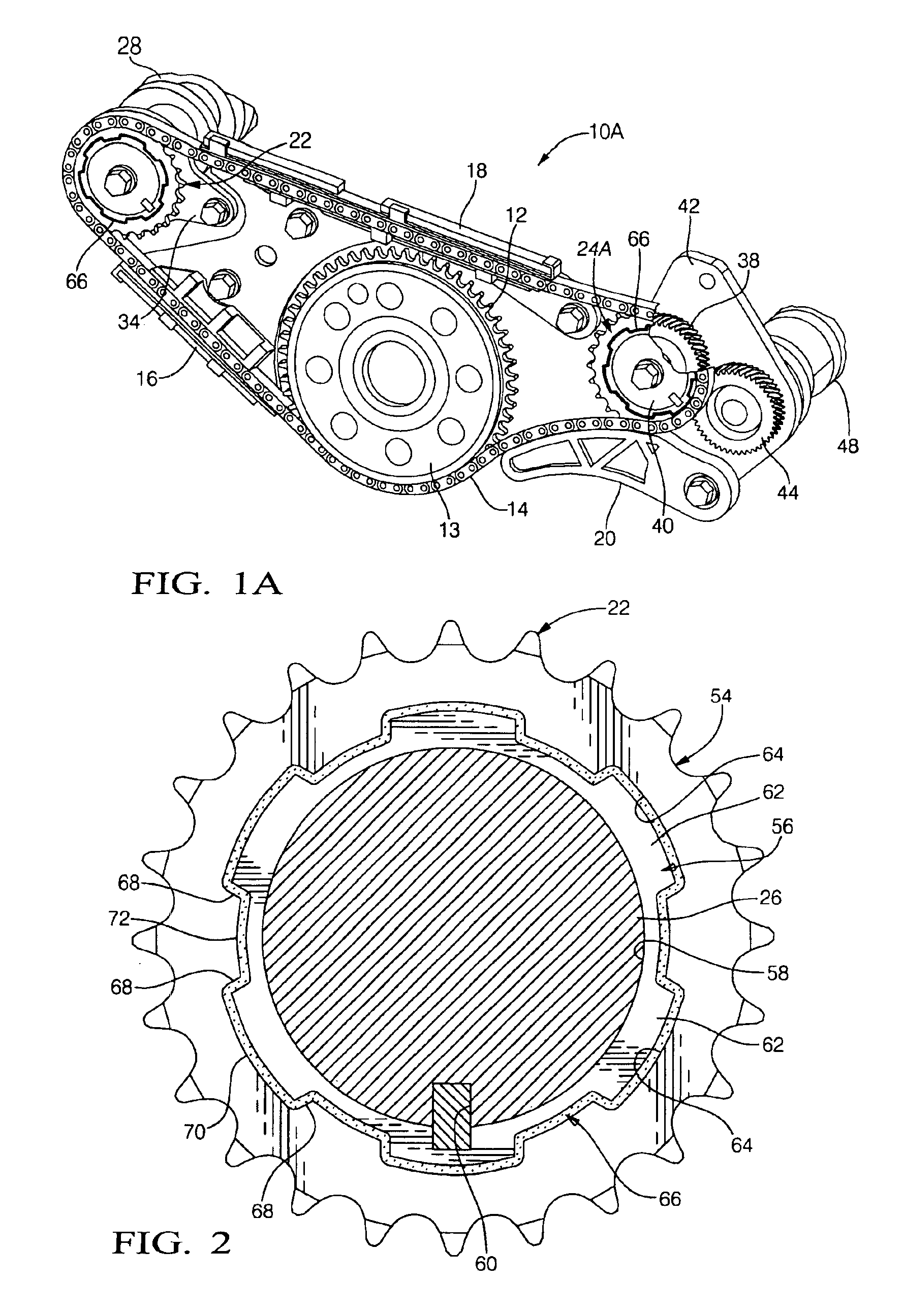
[0012]The balancer 10 includes an engine output sprocket 12, which in assembly is mounted on and rotatable with the engine crankshaft 13, adjacent to the rear end thereof. Sprocket 12 engages a drive chain 14 that runs along guides 16 and 18 and is tensioned by a spring chain tensioner 20. The chain extends laterally in either direction from the sprocket 12 and engages a first input sprocket 22 and a second input sprocket 24.

[0013]The first input sprocket 22 is directly connected to a first balance shaft 26 which includes bearing journals 28 supported in bearings, not shown, mounted to a left side wall of the engine, not shown. Shaft 26 includes front and re...


PUM


Abstract

A chain-driven engine balancer has an elastomeric or compliant isolator ring in a balancer drive sprocket to decouple chain whine vibration from an associated balance shaft. The isolator substantially reduces the transmission of chain whine noise to the engine structure. A splined isolator ring is placed between internal and external splines formed on a toothed outer ring and hub respectively of the associated sprocket. The splines are configured to be in loose engagement so that, upon failure of the elastomeric isolator ring, direct engagement of the hub and ring splines with one another will maintain the timing of the balance shafts with respect to the engine crankshaft. In a specific embodiment, application of an isolator ring in only the most heavily loaded sprocket of dual balance shaft sprockets driven in series by the chain eliminates most of the vibration transmission. However, isolation of multiple chain sprockets could be desirable.

Description

TECHNICAL FIELD[0001]This invention relates to chain-driven engine balancers and, more particularly, to a balancer with a vibration isolation ring in at least one balancer drive sprocket.BACKGROUND OF THE INVENTION[0002]It is known in the art to provide an internal combustion engine having an inherent unbalance condition with an engine mounted balancer driven by the engine crankshaft and rotating in timed relation therewith to offset some or all of the engine unbalance condition. Conventionally the balancer may be driven through a gear or chain drive and may include a single balance shaft or multiple balance shafts. As used in the following specification and claims, the terms “balancer” and “engine balancer” refer to a complete balance system or specified components thereof, including balance shafts or weights and their drive mechanisms, such as chains, drive and driven sprockets, gears and associated or equivalent components. “Engine output shaft” refers to a crankshaft or other ou...

Claims


Application Information

Patent Timeline
IPC IPC(8): F02B75/06F02B75/00F16H55/30F16H55/02F16F15/26F16H55/14
CPCF02B75/06F16F15/265F16H55/30F16H55/14Y10T464/50F16H2055/306Y10T74/2131F16F15/264
Inventor SLOPSEMA, THOMAS ALANBEARDMORE, JOHN MEADE
Owner GM GLOBAL TECH OPERATIONS LLC
Why Eureka
Try Eureka