
Construction of phase change material embedded electronic circuit boards and electronic circuit board assemblies using porous and fibrous media

a technology of phase change material and electronic circuit board, which is applied in the direction of indirect heat exchanger, semiconductor/solid-state device details, lighting and heating apparatus, etc., can solve the problems of small stringers of porous medium, achieve high heat conductivity, enhance the thermal performance of pcm embedded heat sinks, and improve thermal performan

Inactive Publication Date: 2005-11-01
RAYTHEON CO
View PDF35 Cites 29 Cited by
  • Summary
  • Abstract
  • Description
  • Claims
  • Application Information

AI Technical Summary

Benefits of technology

[0007]In accordance with the present invention, there is provided a heat sink having three dimensional properties and capable of providing improved thermal performance relative to the above described prior art systems.
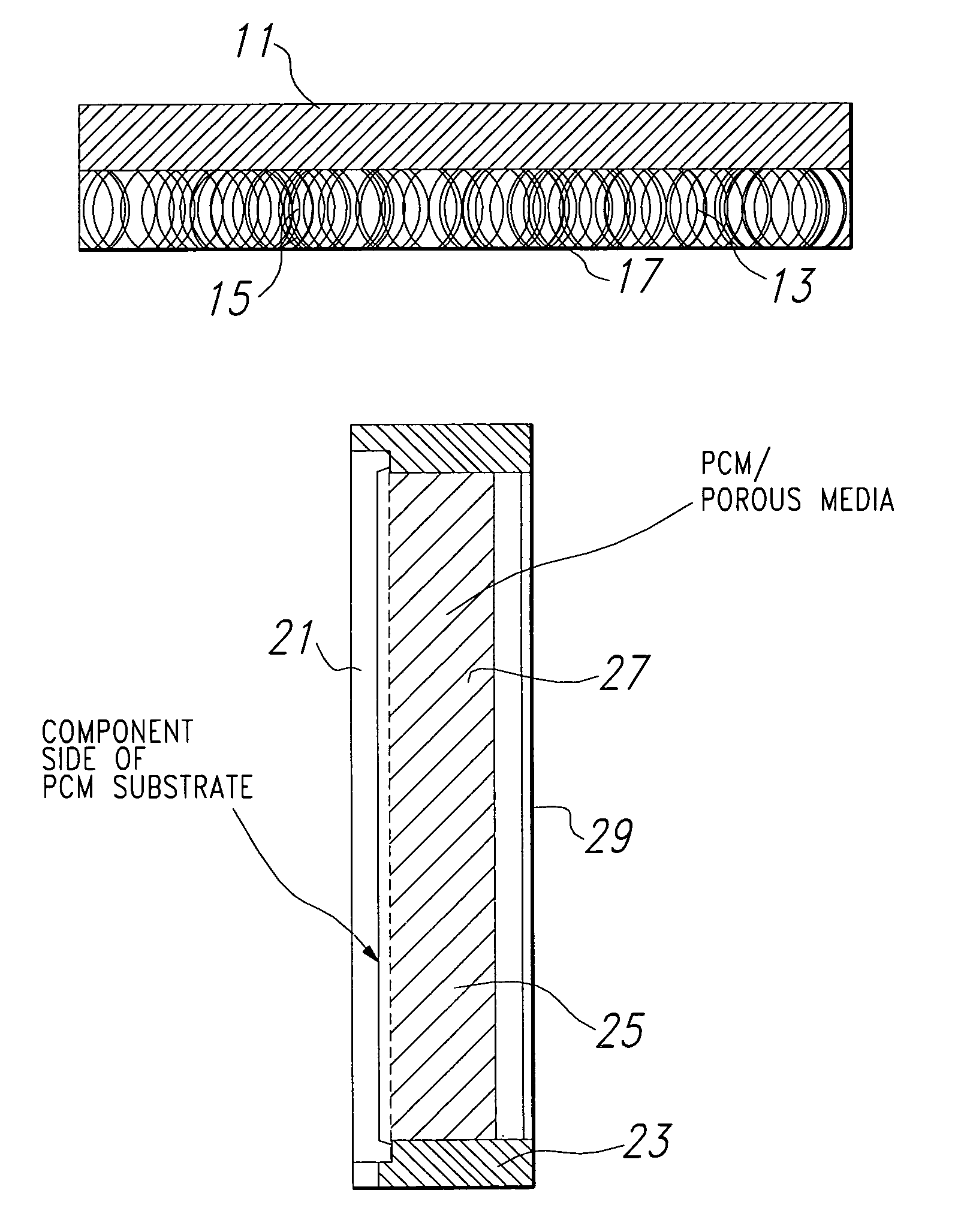
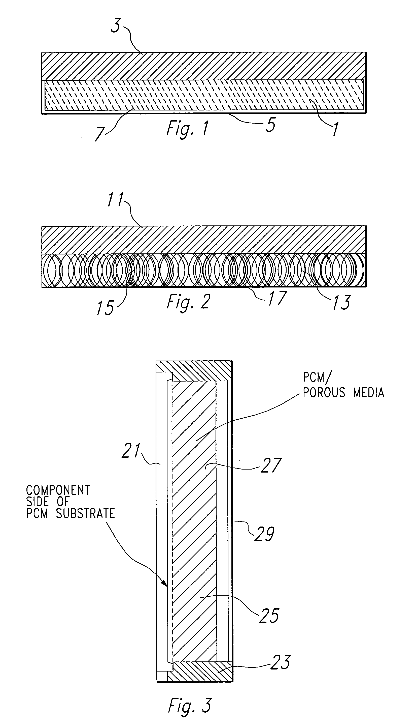
[0010]In accordance with a second embodiment of the invention, the plate of the first embodiment is made of a highly thermally conductive composite fiber material in a matrix, such as, for example, graphite fibers in a matrix of preferably an epoxy, preferably AMOCO K1100X. Composite fibers without matrix extend from the plate into the PCM cavity. These fibers are highly heat conductive and perform the same function as the machined fins and fin stock as discussed hereinabove. However, these fibers can also be arranged so that some of the fibers extend out of the matrix and into the cavity to substantially fill the cavity while also being porous as in the case of the first embodiment. With fibers forming a mat of thermally conductive elements or stringers, the same improvements in thermal performance seen with porous foam media are also realized. Both porous foam media and fibrous media enhance the thermal performance of PCM embedded heat sinks. They can either be stand-alone heat sinks or be integrated with the electrical circuit substrate.

Problems solved by technology

In addition, the porous medium stringers are very small and surround small pockets of PCM.

Method used


Image

  • Construction of phase change material embedded electronic circuit boards and electronic circuit board assemblies using porous and fibrous media
  • Construction of phase change material embedded electronic circuit boards and electronic circuit board assemblies using porous and fibrous media

Examples


Embodiment Construction

[0014]Referring to FIG. 1, porous aluminum medium 1 is vacuum brazed to an aluminum plate 3, which is a heat sink mounting surface, with a cover or lid 5 forming a cavity with the aluminum plate 3 to enclose the porous aluminum medium in the cavity. Heat generators (not shown) are preferably secured to the outer surface of the plate 3 after heat sink fabrication. Once the components of the heat sink are fabricated and assembled, PCM 7 in the form of paraffin is melted and poured into the voids of the porous material 1 and also partially or fully fill the remainder of the cavity. This results in a PCM filled heat sink to which electronic components are mounted. The heat sink can be a stand-alone piece or integrated as part of the electronic circuit board. In an integrated approach, the PCM-filled structure is employed as the substrate upon which circuit layers are built.

[0015]Referring to FIG. 2, the plate 11 is fabricated of a composite fiber material, preferably highly thermally co...


PUM


Abstract

A heat sink which comprises an enclosure having a highly thermally conductive surface region and defining an enclosed cavity. A porous, highly thermally conductive material is disposed in the cavity, preferably homogeneously therein, and is thermally coupled to the thermally conductive surface. A phase change material changing from its initial phase, generally solid, to its final phase, generally liquid, responsive to the absorption of heat is disposed in the enclosed cavity and in the porous material. In accordance with a first embodiment, the highly thermally conductive surface region is preferably aluminum and the porous medium is a highly thermally conductive porous medium, preferably aluminum. In accordance with a second embodiment, the thermally conductive surface is composed of highly thermally conductive fibers disposed in a matrix and the porous material is a plurality of the thermally conductive fibers extending from the thermally conductive surface into the cavity. The highly thermally conductive fibers are preferably graphite and the matrix is preferably an epoxy.

Description

[0001]This application is a Division of application Ser. No. 08 / 406,226, filed Mar. 17, 1995, now abandonded.BACKGROUND OF THE INVENTION[0002]1. Field of the Invention[0003]This invention relates to heat sinks and, more specifically, to heat sinks wherein heat is absorbed by the phase change of a phase change material.[0004]2. Brief Description of the Prior Art[0005]For certain applications, electronic circuit board and component heat sinks are built with embedded phase change material (PCM). Phase change materials for such purposes are well known in the art, an example thereof being a wax which preferably has a unitary melting temperature, paraffins of this type being readily available and well known. The PCM absorbs waste heat as it changes from the solid state to the liquid state. PCMs are also available which can further change from the liquid state to the gaseous state or merely operate in the latter two phase states. Currently, heat sinks which use a PCM are built in several w...

Claims


Application Information

Patent Timeline
IPC IPC(8): F28D20/02H01L23/34H01L23/373H01L23/427
CPCF28D20/02H01L23/3733H01L23/4275Y02E60/145Y10S165/901Y10S165/905Y10S165/902Y10S165/907Y10S165/042H01L2924/0002H01L2924/00Y02E60/14
Inventor WEBER, RICHARD M.RUMMEL, KERRIN A.
Owner RAYTHEON CO
Features
  • Generate Ideas
  • Intellectual Property
  • Life Sciences
  • Materials
  • Tech Scout
  • Unparalleled Data Quality
  • Higher Quality Content
  • 60% Fewer Hallucinations
Learn More