Motor-driven disk brake

a technology of disk brake and motor, which is applied in the direction of electrodynamic brake system, mechanical apparatus, transportation and packaging, etc., can solve the problems of increasing the consumption of electric power for rotating the rotor with age, unable to achieve stable operation, and difficult to release the brake, so as to prevent an increase in the size of the caliper

Active Publication Date: 2005-11-01
HITACHI ASTEMO LTD
View PDF9 Cites 18 Cited by
  • Summary
  • Abstract
  • Description
  • Claims
  • Application Information

AI Technical Summary

Benefits of technology

[0011]If the resilient member is a coil spring wound concentrically with the rotating member or the limiting to store a torsional torque, the resilient member can be accommodated compactly in the caliper. Therefore, it is possible to prevent an increase in size of the caliper.

Problems solved by technology

Consequently, it becomes difficult to release the brake.
Because the amount of rotation of the rotor increases in accordance with the degree of wear of the brake pad, the consumption of electric power for rotating the rotor increases with age.
In addition, because the return force of the spring increases in proportion to the wear of the brake pad, a stable operation cannot be obtained.
Therefore, not only the caliper unavoidably increases in size, but also the production cost increases.
Moreover, there is also possibility that the brake releasing motor itself may fail.
Therefore, the brake lacks reliability.
The scheme disclosed in the patent document 3 suffers from problems such as an increase in power consumption due to the supply of power to the electromagnetic clutch and an increase in cost due to the provision of the electromagnetic clutch.

Method used


Image

  • Motor-driven disk brake
  • Motor-driven disk brake
  • Motor-driven disk brake

Examples


Embodiment Construction

[0017]Embodiments of the present invention will be described below in detail with reference to the accompanying drawings.

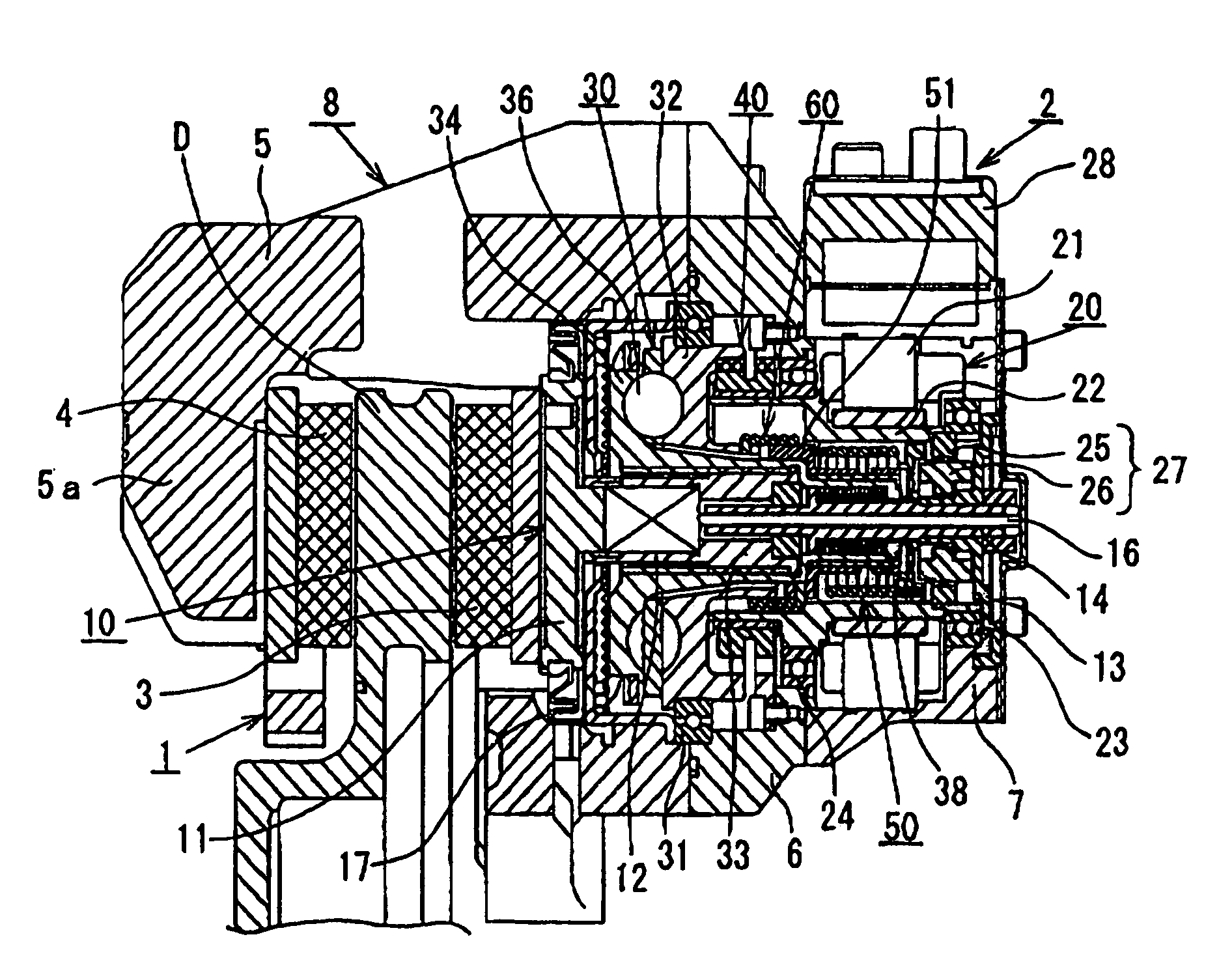
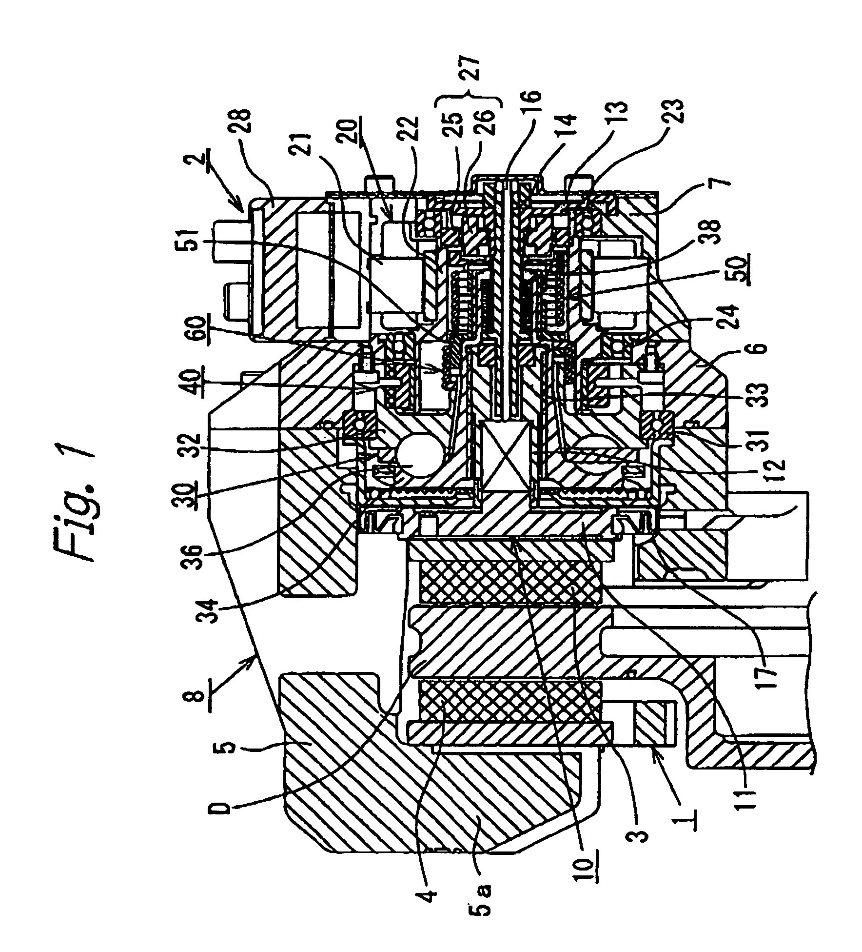
[0018]FIGS. 1 and 2 show a first embodiment of the motor-driven disk brake according to the present inventions. In these figures, a carrier 1 is secured to a non-rotating part (e.g. a knuckle) of a vehicle that is located at the inner side of a disk rotor D relative to the vehicle. A caliper 2 is supported by the carrier 1 so as to be floatingly movable in the axial direction of the disk rotor D. A pair of brake pads 3 and 4 are disposed at both sides of the disk rotor D. The brake pads 3 and 4 are supported by the carrier 1 in such a manner as to be movable in the axial direction of the disk rotor D. The caliper 2 has an assembly type caliper body 8 including a claw member 5 having a claw portion 5a at the distal end thereof. The caliper body 8 further includes an annular base 6 connected to the proximal end of the claw member 5, and a motor casing 7 secured to t...


PUM


Abstract

A motor-driven disk brake having a caliper containing a piston for pressing a brake pad, a rotary actuator and a rotary-to-rectilinear motion converting mechanism for transmitting rotation of the rotary actuator to the piston after converting it into rectilinear motion. The piston is driven in response to rotation of the rotary actuator to press the brake pad against a disk rotor, thereby generating braking force. A brake releasing mechanism for returning the rotary-to-rectilinear motion converting mechanism to its initial position in the event of a failure in the rotary actuator is interposed between a rotating member and a rectilinearly moving member that constitute the rotary-to-rectilinear motion converting mechanism. The brake releasing mechanism has an urging device for generating a torque in the direction for returning the piston in response to the rotation of the rotating member in the direction for advancing the piston. The urging device generates a torque greater than the rotational resistance of the rotating member of the rotary-to-rectilinear motion converting mechanism.

Description

BACKGROUND OF THE INVENTION[0001]The present invention relates to a motor-driven disk brake for generating braking force by using a torque obtained from a rotary actuator. More particularly, the present invention relates to a motor-driven disk brake having a brake releasing function capable of automatically releasing the brake from a lock-up state caused by a failure of the rotary actuator.[0002]A conventional motor-driven disk brake has a caliper containing a piston, a rotary actuator and a motion converting mechanism for transmitting rotation of the rotary actuator to the piston after converting it into rectilinear motion. The piston is driven in response to rotation of the rotary actuator to press a brake pad against a disk rotor, thereby generating braking force in proportion to the torque of the rotary actuator. In this type of motor-driven disk brake, if the rotary actuator fails owing, for example, to disconnection of the power supply line during braking when braking thrust i...

Claims


Application Information

Patent Timeline
Patent Type & Authority Patents(United States)
IPC IPC(8): F16D65/14F16D65/18
CPCF16D65/18F16D65/567F16D2121/24F16D2125/36F16D2125/50F16D2127/02
Inventor USUI, TAKUYA
Owner HITACHI ASTEMO LTD
Why Eureka
Try Eureka