Self-tensioning conveyor
a self-tensioning, conveyor technology, applied in the direction of conveyor parts, mechanical conveyors, transportation and packaging, etc., can solve the problems of reducing the production efficiency of conveyors
- Summary
- Abstract
- Description
- Claims
- Application Information
AI Technical Summary
Benefits of technology
Problems solved by technology
Method used
Image

Examples
second embodiment
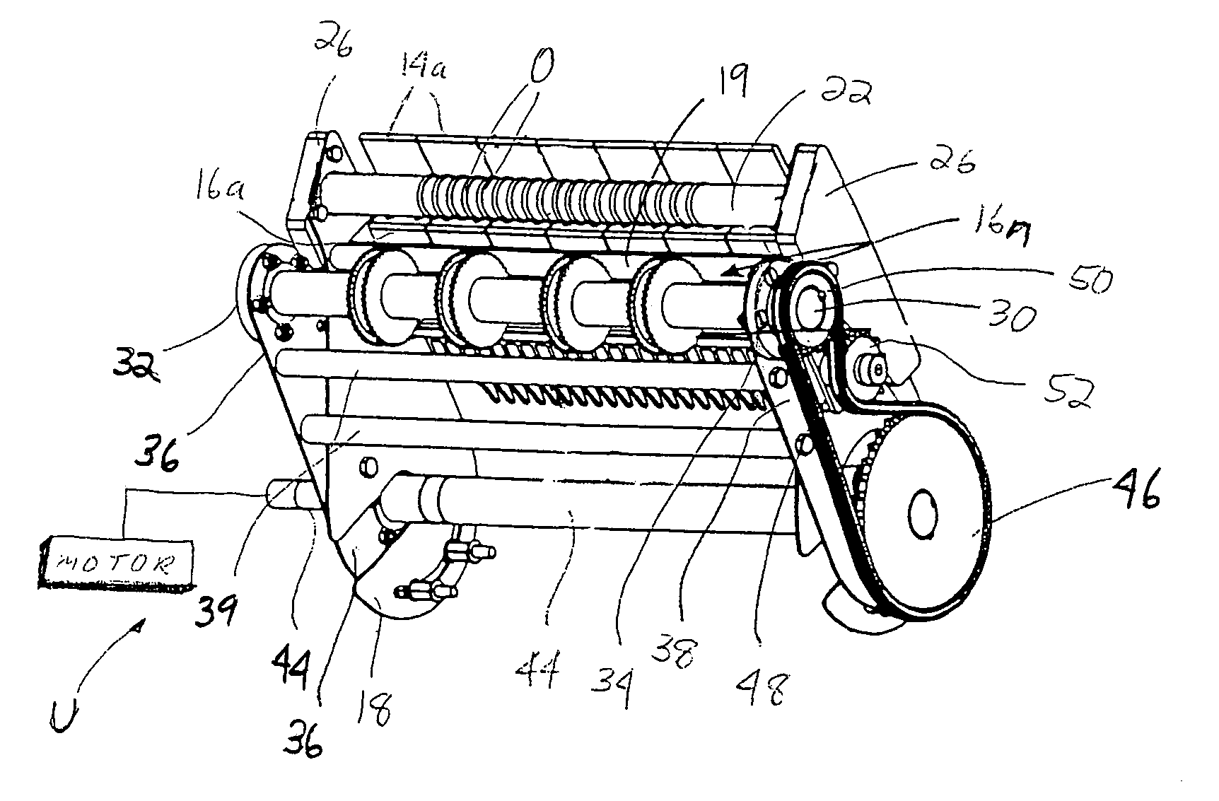
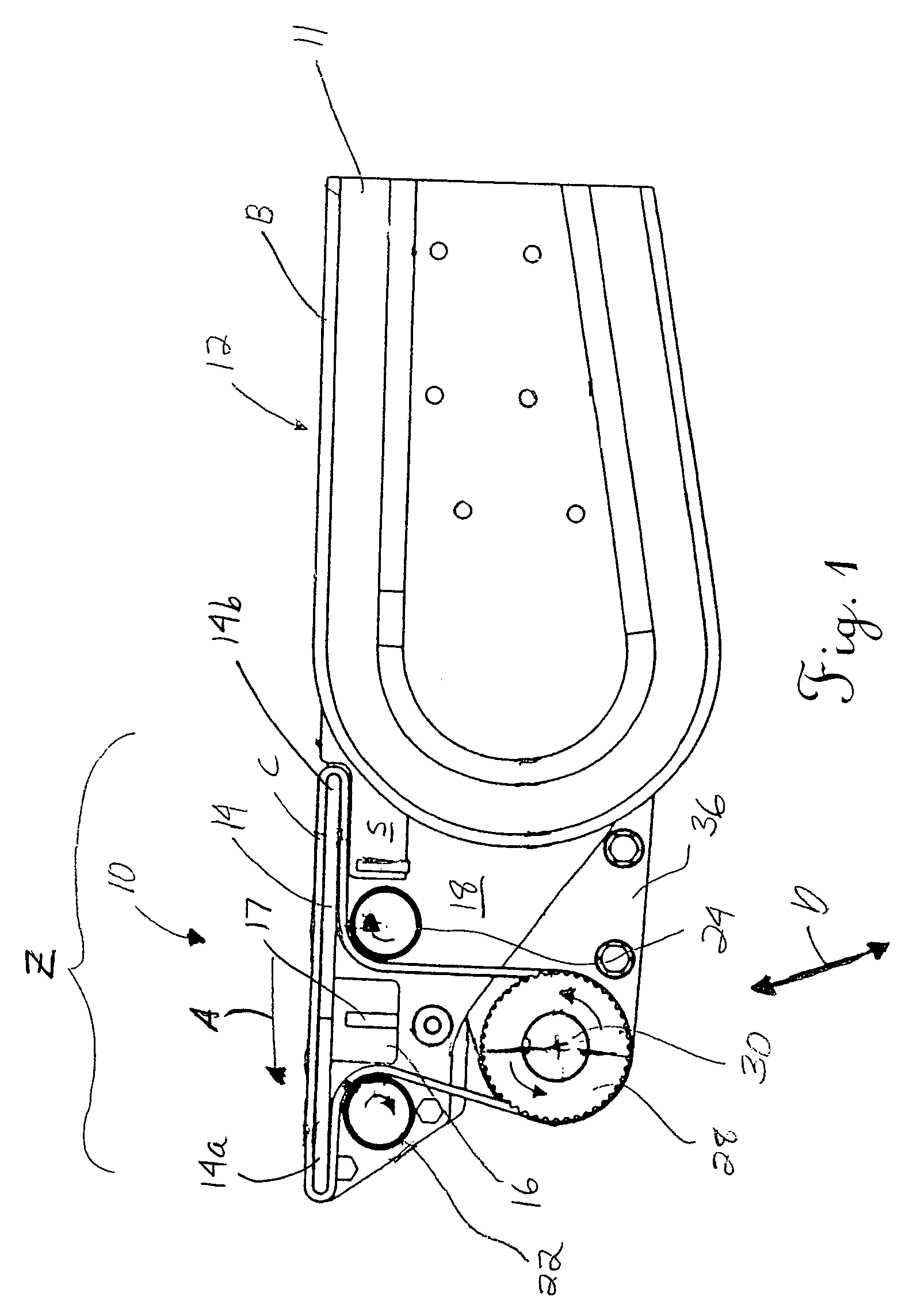
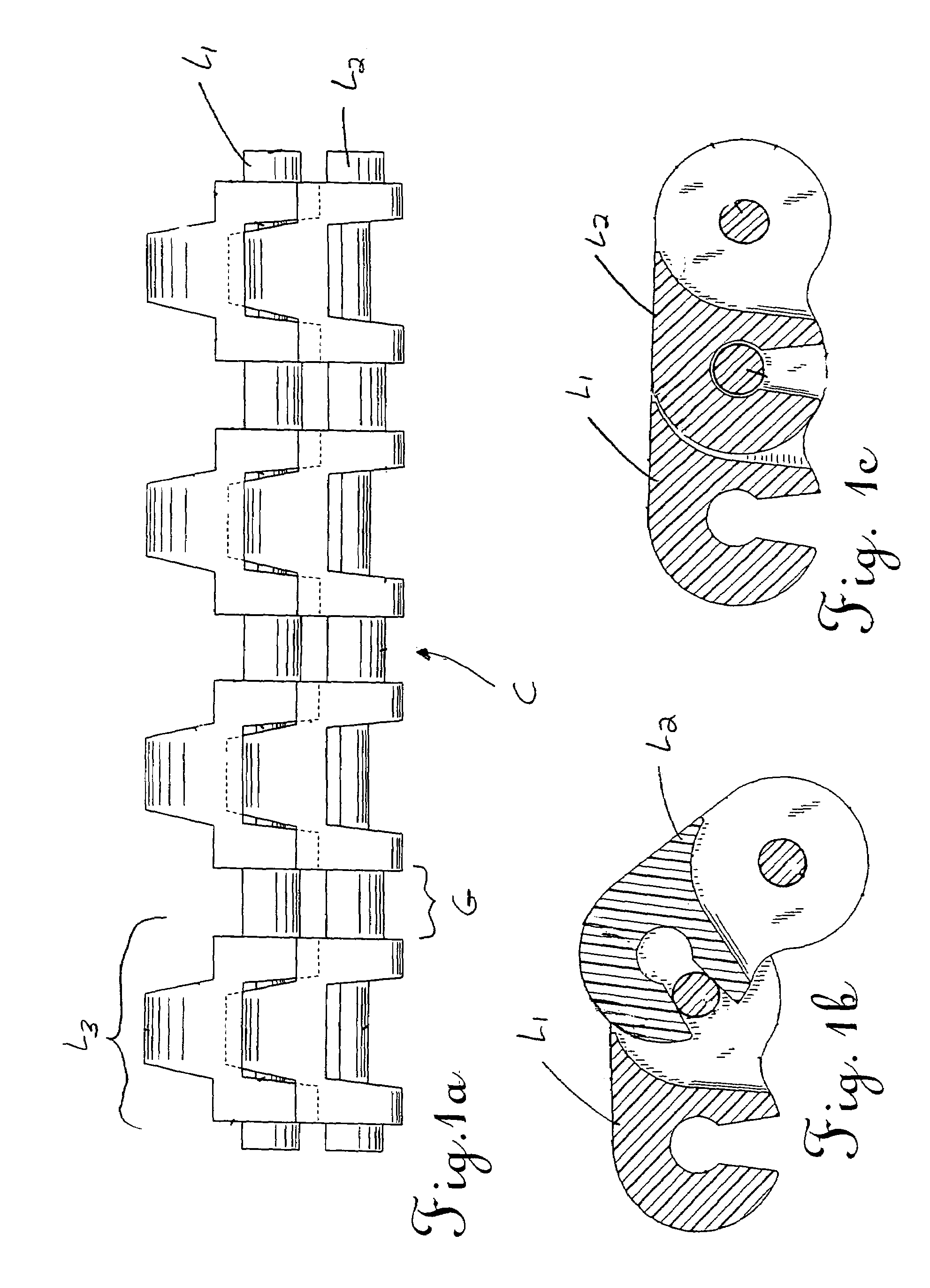
[0072]the driven conveyor 100 forming part of the present invention is shown in FIGS. 8–16. This embodiment is similar in that the conveyor 100 may be positioned in juxtaposition to one end of a conveyor 12 (note bed 11), and includes an endless belt or chain C that may be slave driven by the drive unit U associated with the conveyor (see motor M in FIG. 8 supported from the adjacent conveyor 12 by a bracket K (see FIG. 16)). However, the conveyor 100 of this embodiment does not include any “floating” subassembly for supporting the drive structure.
first embodiment
[0073]Accordingly, instead of using a sprocket 52 for tensioning the drive chain 48 (as is done in the first embodiment as a result of the pivoting movement of the frame members 36, 38 about the transverse axis defined by the drive shaft 44), a pivotally mounted arm 102 supports or carries a camming structure 104. This camming structure 104 may be semi-circular and thus includes a curved or contoured face adapted for engaging an outer surface of the drive chain 48. The force for moving the arm 102 and hence camming structure 104 into engagement with the chain 48 is supplied by a torsion spring 103. As perhaps best shown in FIG. 12, the spring 103 may be mounted over a post P formed in a recess 111 in a housing 110 for the drive subassembly such that one leg 103a engages an adjacent (upper) wall of the housing and the other leg engages the adjacent (upper) surface of the arm 102 and, consequently, moves the camming structure 104 into engagement with the drive chain 48 (see FIGS. 9, 1...
third embodiment
[0081]the conveyor 200 shown in FIG. 17. This embodiment is also adapted for being supported by an adjacent conveyor 12 and slave driven by the corresponding drive unit (not shown). One modification in this embodiment is an adjustment to the manner in which the “floating” idler structure, such as for example roll 24, is tensioned. Specifically, in the embodiment shown in FIG. 17, the chain C is driven in the direction of action arrow A, preferably by slaving the drive shaft 30 to the drive unit of the adjacent conveyor substantially as described above, and the idler structure (roll 24) closest to the adjacent conveyor is mounted for floating movement in a generally horizontal plane, toward the opposite idler structure (roll 22). A pair of side frame members 202 include elongated slots 204 through which the ends of both idler structures or rolls 22, 24 pass. The ends of these structures or rolls 22, 24 extend through an elongated or oblong tensioner bushing 206 connected to and suppo...
PUM
 Abstract
Description
Claims
Application Information
 - Generate Ideas
- Intellectual Property
- Life Sciences
- Materials
- Tech Scout
- Unparalleled Data Quality
- Higher Quality Content
- 60% Fewer Hallucinations
Browse by: Latest US Patents, China's latest patents, Technical Efficacy Thesaurus, Application Domain, Technology Topic, Popular Technical Reports.
© 2025 PatSnap. All rights reserved.Legal|Privacy policy|Modern Slavery Act Transparency Statement|Sitemap|About US| Contact US: help@patsnap.com