
Passive aerodynamic sonic boom suppression for supersonic aircraft

a supersonic aircraft and aerodynamic technology, applied in the field of high-speed aircraft, can solve the problems of aircraft pressure disturbances that move at the speed of sound, aircraft pressure disturbances that stretch out, disturbingly loud sound, etc., to reduce the volume of the mid-fuselage portion, and reduce the disturbance of sonic boom

Inactive Publication Date: 2005-11-01
LOCKHEED MARTIN CORP
View PDF6 Cites 12 Cited by
  • Summary
  • Abstract
  • Description
  • Claims
  • Application Information

AI Technical Summary

Benefits of technology

The patent describes an aircraft that can fly at supersonic speeds. It has a unique design that reduces sonic boom disturbance, which is the noise caused by a sonic boom. The design includes a blunt nose, a fuselage, a wing, and an engine nacelle. The area and lift distribution of the body are tailored to minimize sonic boom disturbance. The mid-fuselage portion is reduced above the wing to create an airflow expansion that lowers the pressure above the wing. This results in a quieter flight and reduced noise for the passengers.

Problems solved by technology

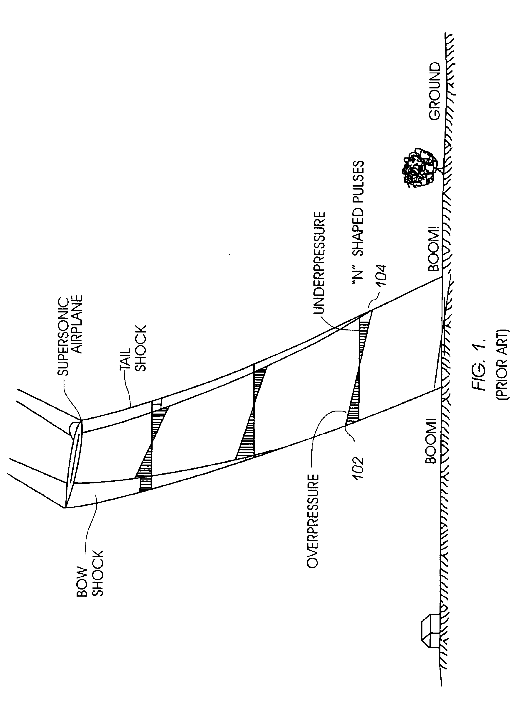
When an object such as an airplane travels through air, the movement of the plane causes a pressure disturbance that moves at the speed of sound.
Since the front of a supersonic aircraft generates an increase in ambient pressure, and the rear generates a decrease in pressure, a corresponding variation in propagation speed causes aircraft pressure disturbances to stretch out as they propagate to the ground.
The abrupt change in pressure can create a disturbingly loud sound.
Additionally, the shock waves may cause structural damage to surrounding buildings.
For these reasons supersonic transports (SST) have been limited to routes that do not carry the plane across land.
SSTs are therefore restricted to flights across water, thereby limiting the usefulness of the planes.

Method used


Image

  • Passive aerodynamic sonic boom suppression for supersonic aircraft
  • Passive aerodynamic sonic boom suppression for supersonic aircraft
  • Passive aerodynamic sonic boom suppression for supersonic aircraft

Examples


Embodiment Construction

[0030]The following description is provided to enable any person skilled in the art to make and use various embodiments of the invention, and sets forth the best modes contemplated by the inventor of carrying out the various embodiments disclosed.

[0031]Various embodiments disclosed herein use a combination of synergistic techniques to achieve reduction of the sonic boom from supersonic airplanes. A reduction of noise from sonic booms by at least 15-25 decibels is achieved while reducing the drag of a reduced boom vehicle and maintaining a practical design.

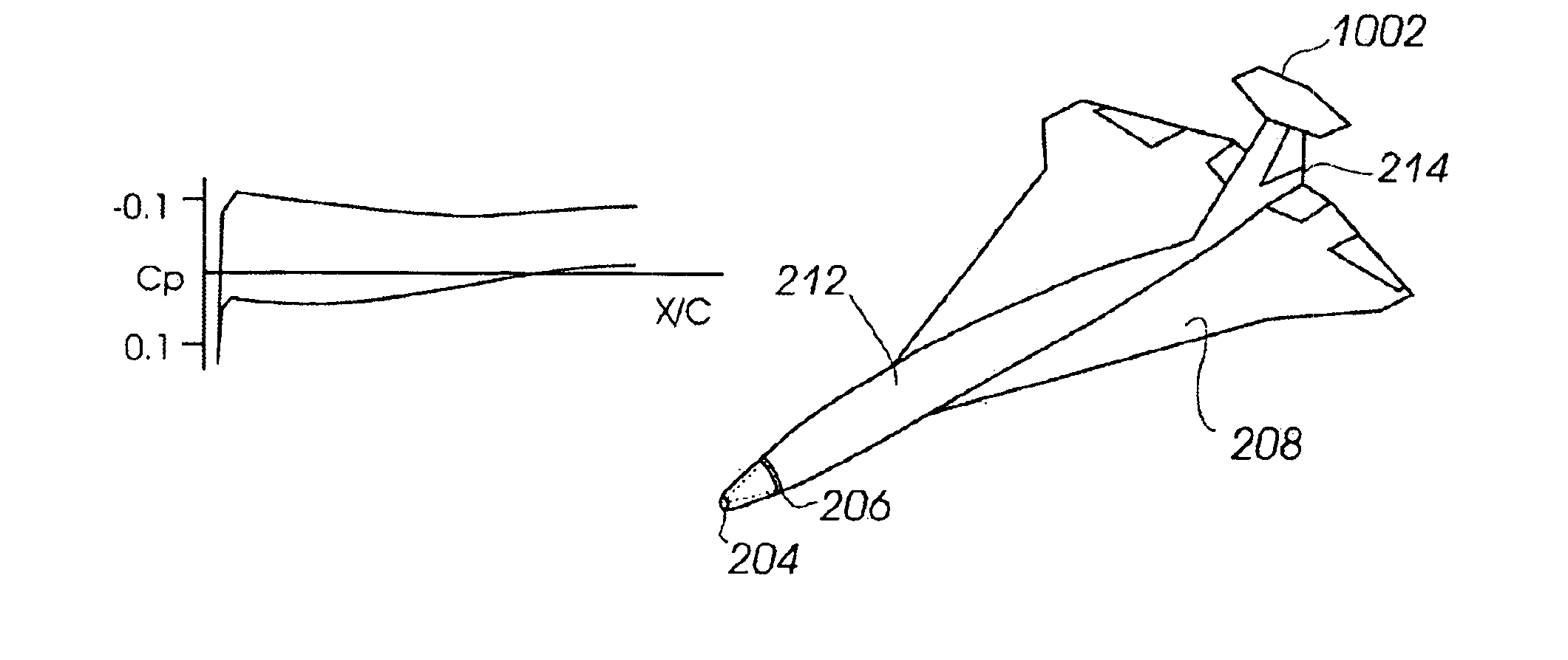
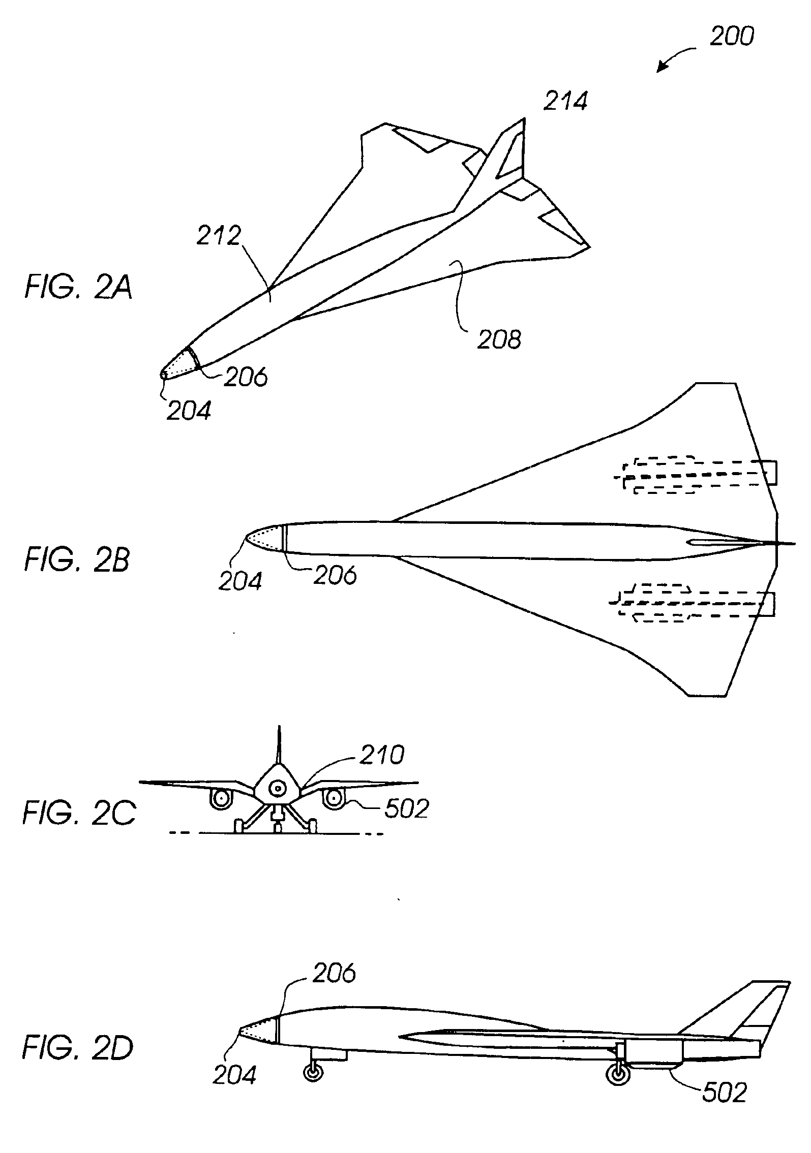
[0032]FIGS. 2A through 2D illustrate an embodiment of an aircraft 200 configured to minimize sonic boom disturbances. Aircraft 200 includes features that compress the pressure at the nose, expand pressure at the tail, and constrain the pressures between the nose and tail to weak compressions and expansions to prevent the pressure waves from coalescing. As a result, aircraft 200 can fly at supersonic speeds with significantly reduce...


PUM


Abstract

An aircraft capable of supersonic flight comprises a body portion including a fuselage, a wing, and an engine nacelle mounted below the wing. The aircraft may also include a high-mounted aft, tail. The area / lift distribution of the body portion is tailored to reduce sonic boom disturbance. The body portion further includes a blunt nose and a gull dihedral wing configuration that further reduces sonic boom disturbance and eases constraints on area / lift distribution tailoring. The gull dihedral wing or tail is configured to carry lifting force to its trailing edge to create an expansion at the aft end of the aircraft that reduces aft sonic boom ground shock strength. The volume of the mid-portion of the fuselage can be reduced above the wing to create a sloped surface that generates an expansion fan over the wings. The expansion fan lowers the pressure above the wing in the area covered by the expansion to reduce the pressure required on the upper and lower surfaces of the wing to generate the same lifting force.

Description

CROSS-REFERENCE TO RELATED APPLICATION[0001]This application is a continuation-in-part of U.S. Ser. No. 09 / 499,654 filed Feb. 8, 2000, now U.S. Pat. No. 6,588,703 entitled “Passive Aerodynamic Sonic Boom Suppression for Supersonic Aircraft”, issued Jul. 8, 2003 and is a continuation-in-part of U.S. Ser. No. 10 / 006,505 filed Dec. 6, 2001, now U.S. Pat. No. 6,729,577.BACKGROUND[0002]1. Field of Invention[0003]The present invention relates generally to high-speed aircraft, and more particularly to long range supersonic cruise aircraft having sonic boom shock suppression capabilities.[0004]2. Description of the Related Art[0005]When an object such as an airplane travels through air, the movement of the plane causes a pressure disturbance that moves at the speed of sound. By way of example, the sound waves created by the nose of the plane will travel in an outward direction away from the aircraft. The air ahead of the plane receives the sound waves before the arrival of the aircraft, so ...

Claims


Application Information

Patent Timeline
Patent Type & Authority Patents(United States)
IPC IPC(8): B64C23/00B64C23/04B64C30/00
CPCB64C23/04B64C30/00
Inventor HARTMANN, TOMMORGENSTERN, JOHN M.
Owner LOCKHEED MARTIN CORP
Learn More