Passenger detection system and detection method

a passenger and detection system technology, applied in the direction of pedestrian/occupant safety arrangement, instruments, tractors, etc., can solve the problems of inability to evaluate the passenger seating conditions, the effect of reducing design freedom, reducing cost, and eliminating the signal error in evaluating the passenger seating conditions

Inactive Publication Date: 2005-11-01
HONDA ELESYS CO LTD
View PDF3 Cites 55 Cited by
  • Summary
  • Abstract
  • Description
  • Claims
  • Application Information

AI Technical Summary

Benefits of technology

[0090]In this case, the signal line in the shield cable and the buffer circuit connected to the shield line are connected to an operational amplifier to maintain the same potential in the signal line and the shield line. This buffer circuit the signal levels in the com circuit are maintained at the same potential level so that the RC time constant between the signal and shield lines does not affect the signal communication between the control circuits and the signal error in evaluating the passenge

Problems solved by technology

However, this type of airbag apparatus is designed so that the airbags are deployed upon collision, regardless of the presence of a passenger so that, when an adult is sitting on the passenger seat, protective effect against collision can be expected, but when a child is sitting on the passenger seat, because the seated height is shorter and the head position is lower than an adult, the effect of airbag deployment on the child can be more damaging.
However, body w

Method used


Image

  • Passenger detection system and detection method
  • Passenger detection system and detection method
  • Passenger detection system and detection method

Examples


embodiment 1

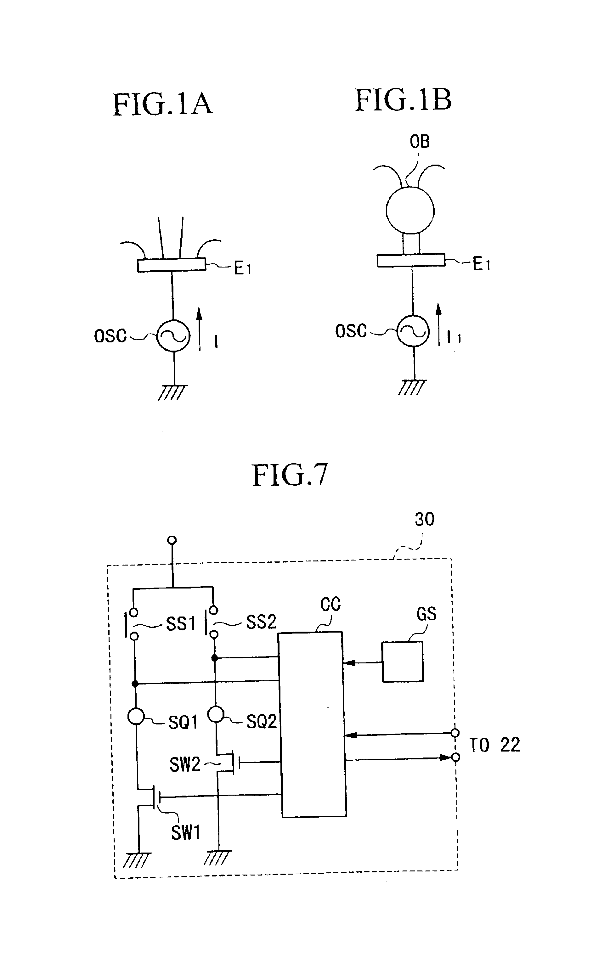
[0190]The basic principle of the passenger detection system will be explained with reference to FIG. 1. The present detection system is based on perturbation in weak electric field generated by the presence of an object in the vicinity of antenna electrode. First, as shown in FIG. 1A, when a high frequency low voltage (HFLV) signal is impressed on an antenna E1 by an oscillation circuit OSC, a weak electric field is generated in the vicinity of the electrode, resulting in a flow of current I in the antenna electrode E1. When an object OB is introduced in the vicinity of the antenna electrode E1, as shown in FIG. 1B, the electric field is disturbed, resulting in a perturbation current I1, which is different in character than current I.

[0191]Therefore, by utilizing the fact that the different currents flow in antenna electrode E1, depending on there is or there is no object OB on a vehicle seat, it is possible to detect the seating condition of the passenger. Specially, by increasing ...

embodiment 2

[0222]Next, Embodiment 2 will be presented using the same reference numerals as those in Embodiment 1 for those parts that are the same, and their explanations are omitted. The passenger detection system in this embodiment is based on detecting the perturbation current related to passenger seating conditions by comparison of reference data with detected data and using improved switching methods.

[0223]As shown in FIG. 5, a control unit 10 is disposed on the seat frame 3 or its vicinity, and this control unit 10 is comprised by, for example: an electric field generation device (oscillator and the like) 11 for generating a weak electric field; an amplitude control circuit 12 for controlling the amplitude of the forward signal from the oscillation circuit 11 to antenna electrode 4 approximately constant; an information detection circuit (current detection circuit for example) 15 for detecting information on the forwarding current of the forward signal; an ac-dc conversion circuit 16 for...

embodiment 3

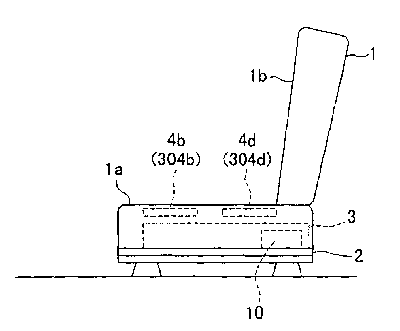
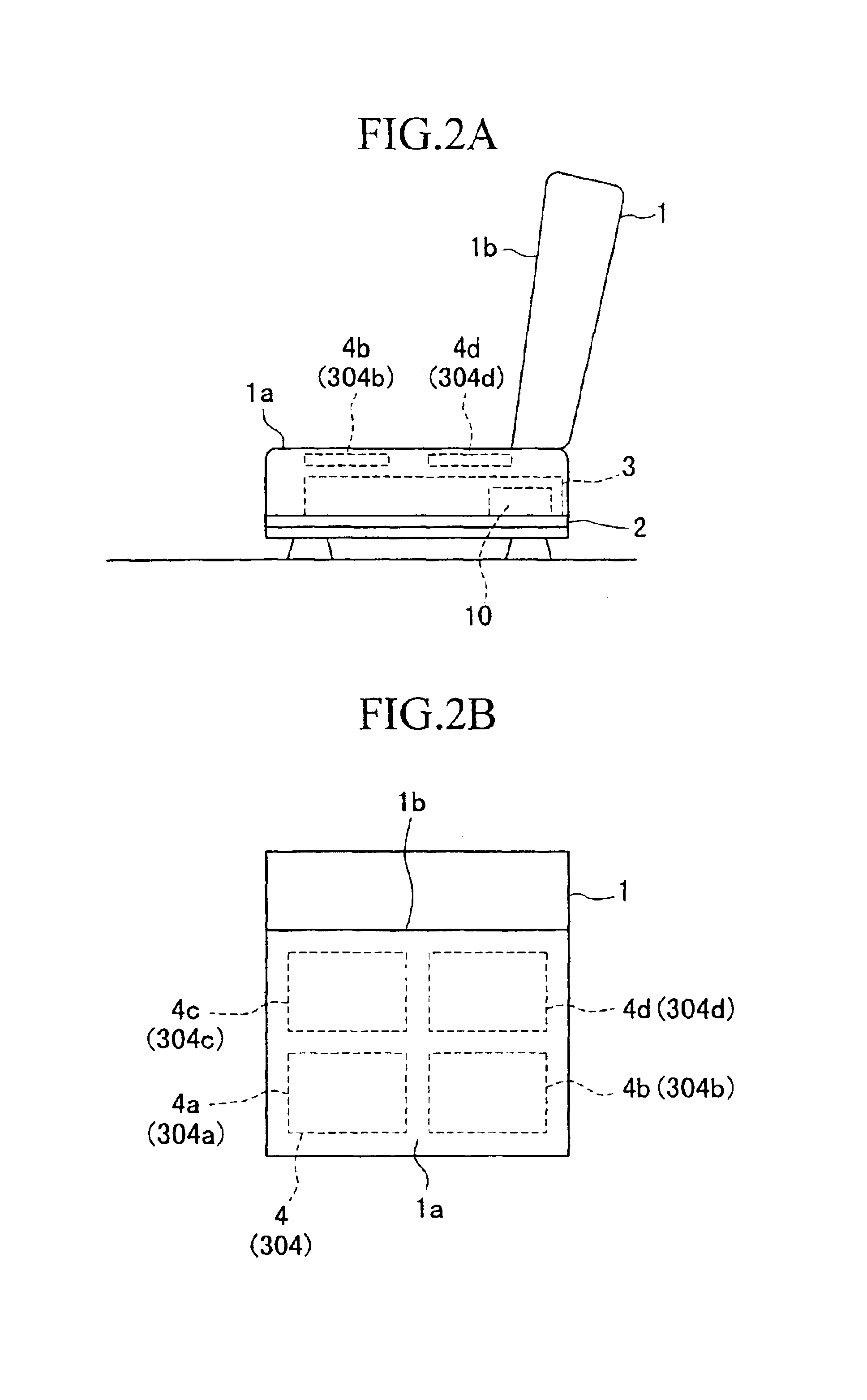
[0239]Next, the passenger detection system in Embodiment 3 will be presented with reference to the drawings. The passenger detection system in this embodiment is based on detecting the perturbation current related to passenger seating conditions more effectively by using an impedance matching circuits and various designs of antenna electrodes. Those parts which are the same as the parts shown in FIGS. 96˜97 will be given the same reference numerals and their detailed explanations will be omitted. FIGS. 2, 21 show the arrangement of the passenger seat 1 and the antenna electrodes, and seat 1 is comprised primarily of a sitting section 1a and a backrest section 1b. The sitting section 1a is comprised by a seat frame 3 fixed to the base 2 which can be moved forward and backward, and an outer covering for the cushion. Particularly, a plurality of antenna electrodes 304 of substantially the same shape (for example, rectangular spiral), separated at some distance, are disposed symmetrical...


PUM


Abstract

A passenger detection system is presented so that the master control circuit in the system instructs the passenger airbag control circuit controlling the operation of the airbag designated for the passenger seat to be in the deployable state or not-deployable state, depending on the seating conditions of a passenger sitting on the passenger seat, for example whether the passenger is an adult or a child. The passenger detection system is operated by a plurality of antenna electrodes disposed on the passenger seat; an electric field generation device for generating an electric field around an antenna electrode; a switching circuit for connecting the electric field generation device to the various antenna electrodes; an information detection circuit for detecting information related to a current flowing in a particular antenna electrode selected by the switching circuit; a master control circuit for receiving signal data output from the information detection circuit, and judging passenger seating conditions according to the signal data; and an airbag apparatus for controlling the operation of an airbag designated for the driver seat and an airbag designated for the passenger seat.

Description

CROSS REFERENCE TO RELATED APPLICATION[0001]This application is a divisional of application Ser. No. 09 / 395,046, filed Sep. 13, 1999, now U.S. Pat. No. 6,559,555 the contents of which are incorporated herein by reference.BACKGROUND OF THE INVENTION[0002]1. Field of the Invention[0003]The present invention relates in general to passenger detection systems and methods, and relates in particular to an improved passenger detection system that places the airbag for the passenger, in the deployable or not-deployable state, depending on the seating conditions of the passenger sitting in the passenger seat in an automobile.[0004]This application is based on Japanese Patent Applications Nos. Hei 10-061299, Hei 10-077870, Hei 10-077871, Hei 10-077872, Hei 10-077873, Hei 10-083797, Hei 10-083798, Hei 10-083799, Hei 10-097782, and Hei 10-153270, the contents of which are incorporated herein by reference.[0005]2. Description of the Related Art[0006]In general, an airbag apparatus in an automobil...

Claims


Application Information

Patent Timeline
IPC IPC(8): B60R21/01B60R21/015B60R21/33
CPCB60R21/01532B60R21/0154B60R21/33
Inventor SAITOU, TAKASHIOFUJI, MASAHIROOKA, YOSHITAKAJINNO, KAZUNORI
Owner HONDA ELESYS CO LTD
Why Eureka
Try Eureka