Switching power supply

a power supply and switching technology, applied in the field of switching power supply, can solve the problems of reducing power supply efficiency, generating loss from switching operation of switching element b>1, and lighter load, so as to reduce power supply output standby power consumption, improve power supply efficiency, and reduce current loss

Inactive Publication Date: 2005-11-01
PANASONIC CORP
View PDF8 Cites 38 Cited by
  • Summary
  • Abstract
  • Description
  • Claims
  • Application Information

AI Technical Summary

Benefits of technology

[0050]The present invention is devised to solve the above conventional problems and has as its object the provision of a switching power supply which reduces a switching operation period on standby, reduces current loss during a switching operation, reducing power consumption on standby for output from a power supply, and improves power supply efficiency.
[0056]As described above, the present invention comprises a standby detection circuit for stopping and resuming the switching operation repeatedly turning on / off performed by the switching element in a standby state. Thus, the standby detection circuit can stop the switching operation of the switching element at the start of a standby mode where the output voltage of the IV converter exceeds the standby detection upper limit voltage from the reference voltage source, and the standby detection circuit can resume the switching operation of the switching element when the output voltage of the IV converter is reduced by the stop along with the power supply output voltage and is lower than the standby detection lower limit voltage from the reference voltage source.
[0057]Hence, it is possible to reduce a switching period in a standby mode, reduce current loss during the switching operation, reduce the standby power consumption of the power supply output, and improve power supply efficiency.
[0059]Thus, it is possible to reduce current loss when the switching operation is stopped and resumed during a standby mode, reduce the standby power consumption of the power supply output, and improve power supply efficiency.

Problems solved by technology

Therefore, even at no load, a loss is generated by the switching operation of the switching element 1.
A lighter load increases a loss on the switching element 1 and reduces efficiency on the power supply.
Thus, it is not possible to meet the need for lower power consumption during the standby mode of the power supply.

Method used


Image

  • Switching power supply
  • Switching power supply
  • Switching power supply

Examples


Embodiment Construction

[0070]A switching power supply according to the embodiment of the present invention will be specifically described below with reference to the accompanying drawings.

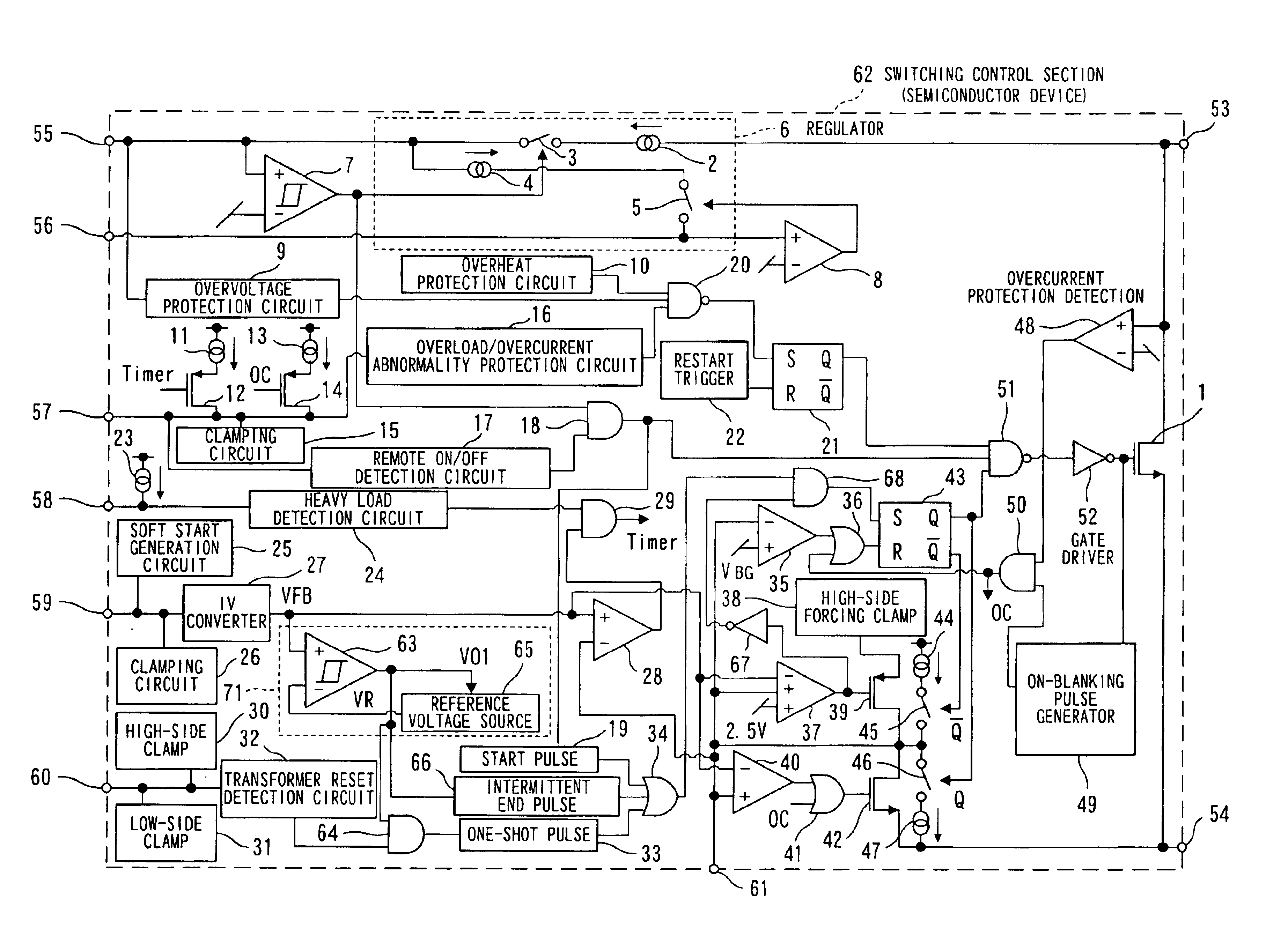
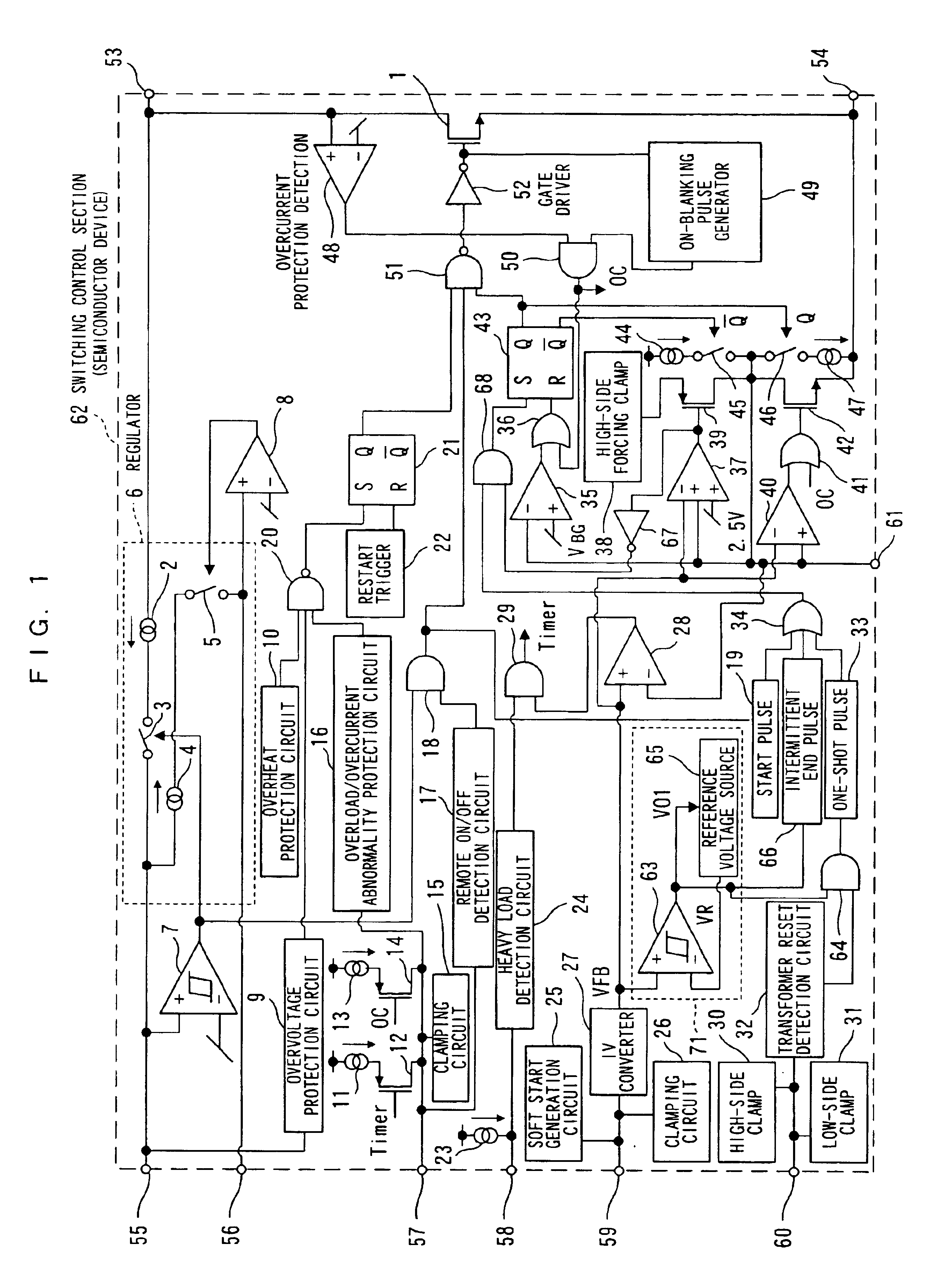
[0071]FIG. 1 is a circuit block diagram showing a structural example of a switching control section in the switching power supply according to the present embodiment. The same constituent elements as the switching control section of FIG. 7 are indicated by the same reference numerals and the explanation thereof is omitted. As with the switching control section of FIG. 7, a switching control section 62 of FIG. 1 is constituted as a semiconductor device (hereinafter, the switching control section will be indicated as a semiconductor device) and comprises a standby detection circuit 71 supplied with the output of an IV converter 27 for performing voltage conversion on current fed from a control terminal 59.

[0072]The standby detection circuit 71 comprises a standby detection comparator 63. An output voltage VFB outputted fro...


PUM


Abstract

The present invention provides a switching power supply which reduces power consumption in a standby state and improves power supply efficiency. At the time of starting a standby mode in which the output voltage VFB of the IV converter exceeds a standby detection upper limit voltage from a reference voltage source, the switching operation of the switching element is stopped. This stopping reduces the output voltage VFB of the IV converter along with a power supply voltage VO. When the output voltage VFB is lower than a standby detection lower limit voltage from the reference voltage source, the switching operation of the switching element is resumed.

Description

FIELD OF THE INVENTION[0001]The present invention relates to a switching power supply whereby direct-current output voltage is stabilized by controlling a switching operation when the direct-current output voltage obtained by the switching operation is fed to a load.BACKGROUND OF THE INVENTION[0002]Conventionally switching power supplies are widely used, each serving as a power source supply installed in office automation equipment such as a personal computer. In such a power supply, switching is performed on direct-current input voltage by a switching element, alternating voltage generated by the switching operation via a transformer is rectified and smoothed to output direct-current input voltage, and when the direct-current output voltage is fed to a load, the switching operation of the switching element is controlled by a control circuit according to a change in direct-current output voltage, so that direct output voltage is stabilized.[0003]The above conventional switching powe...

Claims


Application Information

Patent Timeline
Patent Type & Authority Patents(United States)
IPC IPC(8): H02M3/335H02M3/24H02M3/28
CPCH02M3/33523
Inventor YAMASHITA, TETSUJI
Owner PANASONIC CORP
Why Eureka
Try Eureka