Method and circuit for driving electrophoretic display, electrophoretic display and electronic device using same

a technology of electrophoretic display and electrophoretic display, applied in the field of electrophoretic display, can solve the problems of poor viewing characteristics and prior art electrophoretic display, and achieve the effect of improving display image characteristics

Inactive Publication Date: 2005-11-01
E INK CORPORATION
View PDF33 Cites 25 Cited by
  • Summary
  • Abstract
  • Description
  • Claims
  • Application Information

AI Technical Summary

Benefits of technology

[0012]In the present invention, to further improve display image characteristics, it is preferable for there to be variations in the properties of pigment particles employed, such as charge and mass. As noted above, in the present invention pigment particles do not need to be initialized before a display update is made. This helps to overcome a problem which conventional electrophoretic displays suffer from, whereby after a voltage differential between electrodes is cancelled, pigment particles continue to move under their inertia. This residual movement of pigment particles causes fluctuations in an image displayed. In the case that minimal fluid resistance acts against pigment particles, inertial movement of the particles and resulting display fluctuations become pronounced. To overcome this problem of inertial particle movement, in the method of the present invention, after a differential voltage is applied to a second electrode, a further ‘brake’ voltage is applied to the dielectric fluid to stop movement of the pigment particles rapidly. Since a direction of motion of a particle is determined by a direction and polarity of an applied electrostatic field, a brake voltage to be applied has a polarity which is opposite to that of a voltage applied to a pixel electrode. Different from prior art displays, in the electrophoretic

Problems solved by technology

However, prior art electrophoretic displays suffer from a

Method used


Image

  • Method and circuit for driving electrophoretic display, electrophoretic display and electronic device using same
  • Method and circuit for driving electrophoretic display, electrophoretic display and electronic device using same
  • Method and circuit for driving electrophoretic display, electrophoretic display and electronic device using same

Examples


first embodiment

[0058](A) First Embodiment

[0059]An electrophoretic display of the present embodiment displays an image according to an input image signal (VID). It is able to display both static and animated images, but is particularly suited to displaying static images.

[0060](A-1) Outline of an Electrophoretic Display

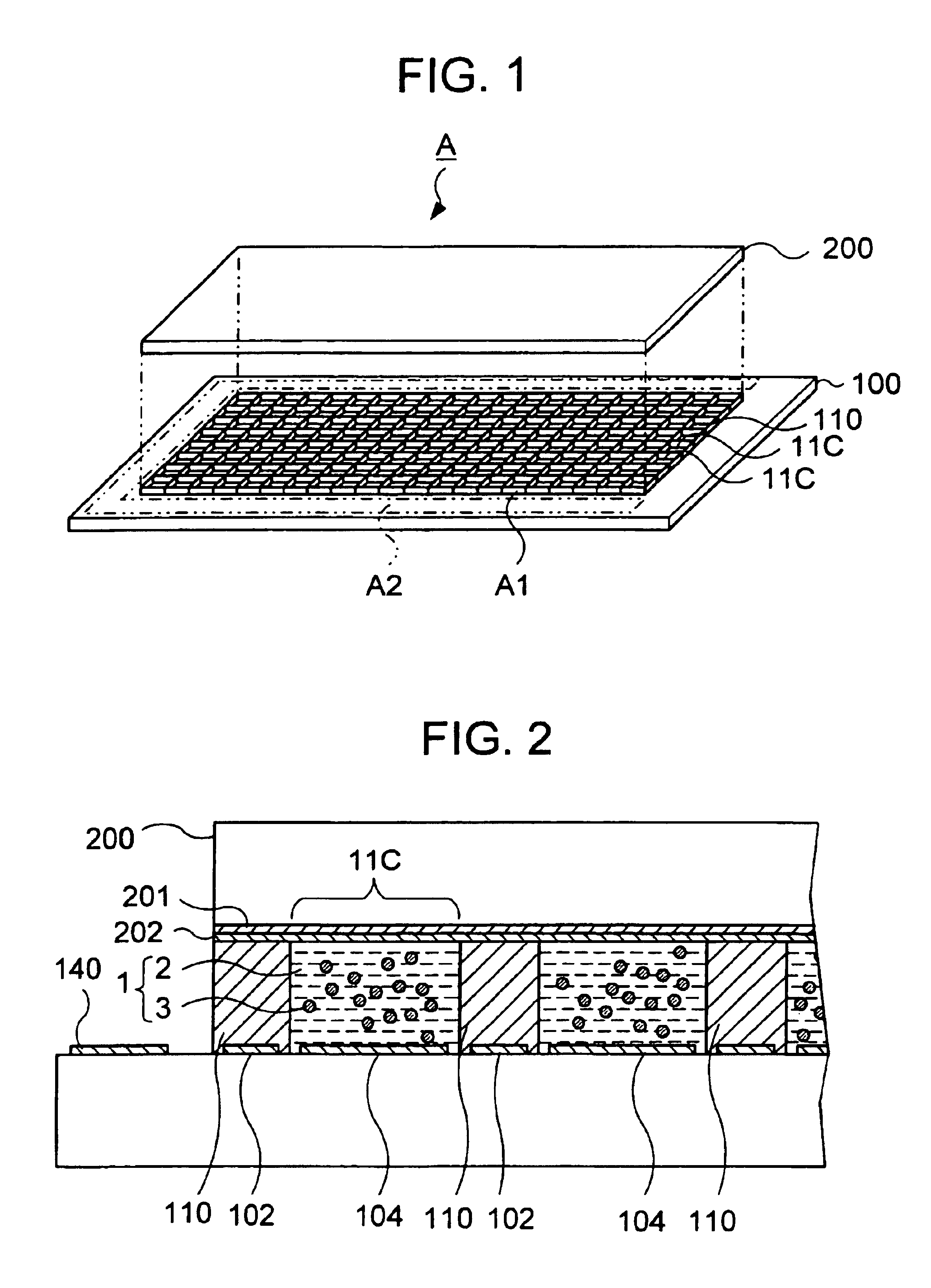
[0061]FIG. 1 is an exploded perspective view showing the mechanical configuration of an electrophoretic display panel A, according to the first embodiment of the present invention.

[0062]FIG. 2 is a partial sectional view of the panel.

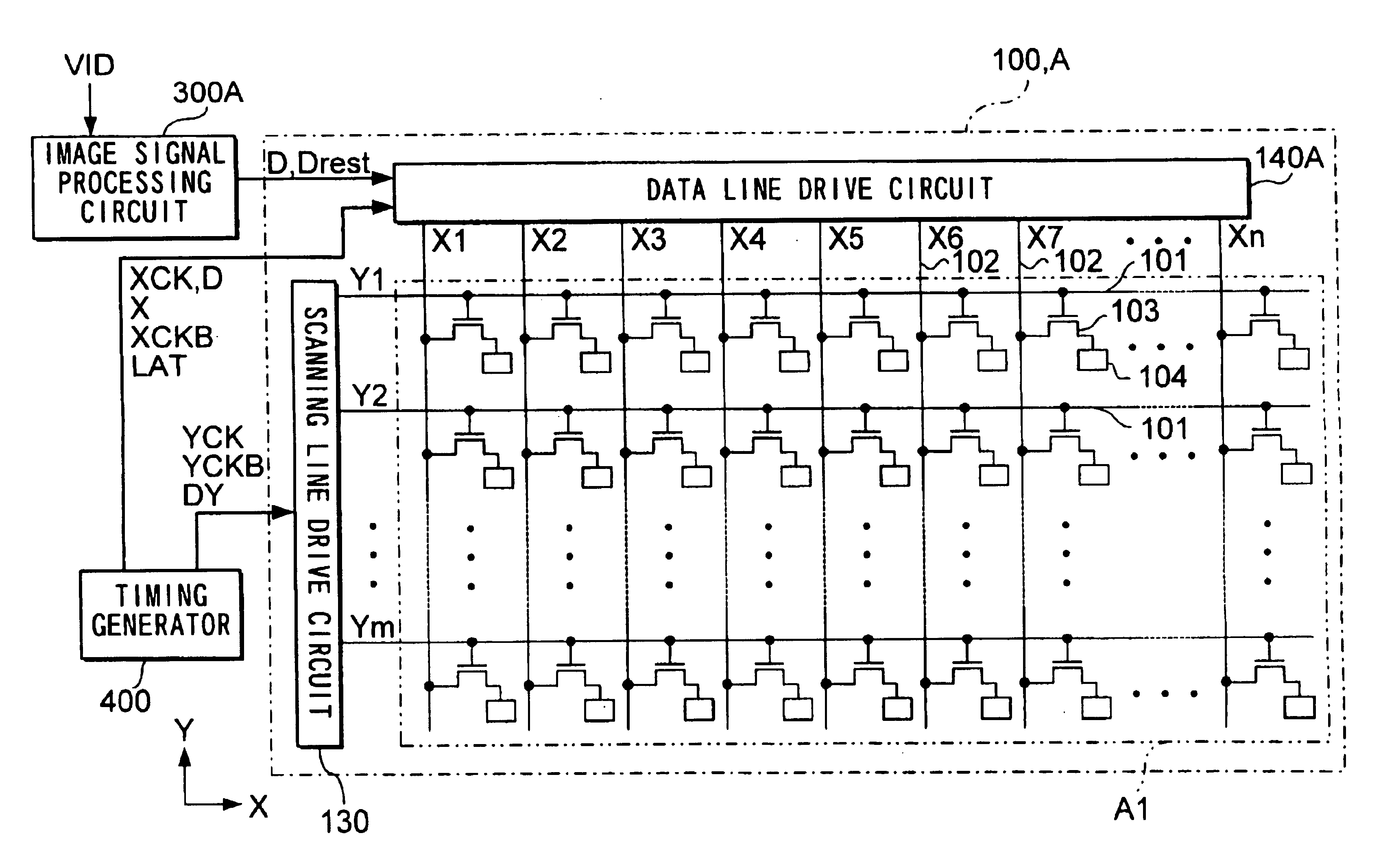
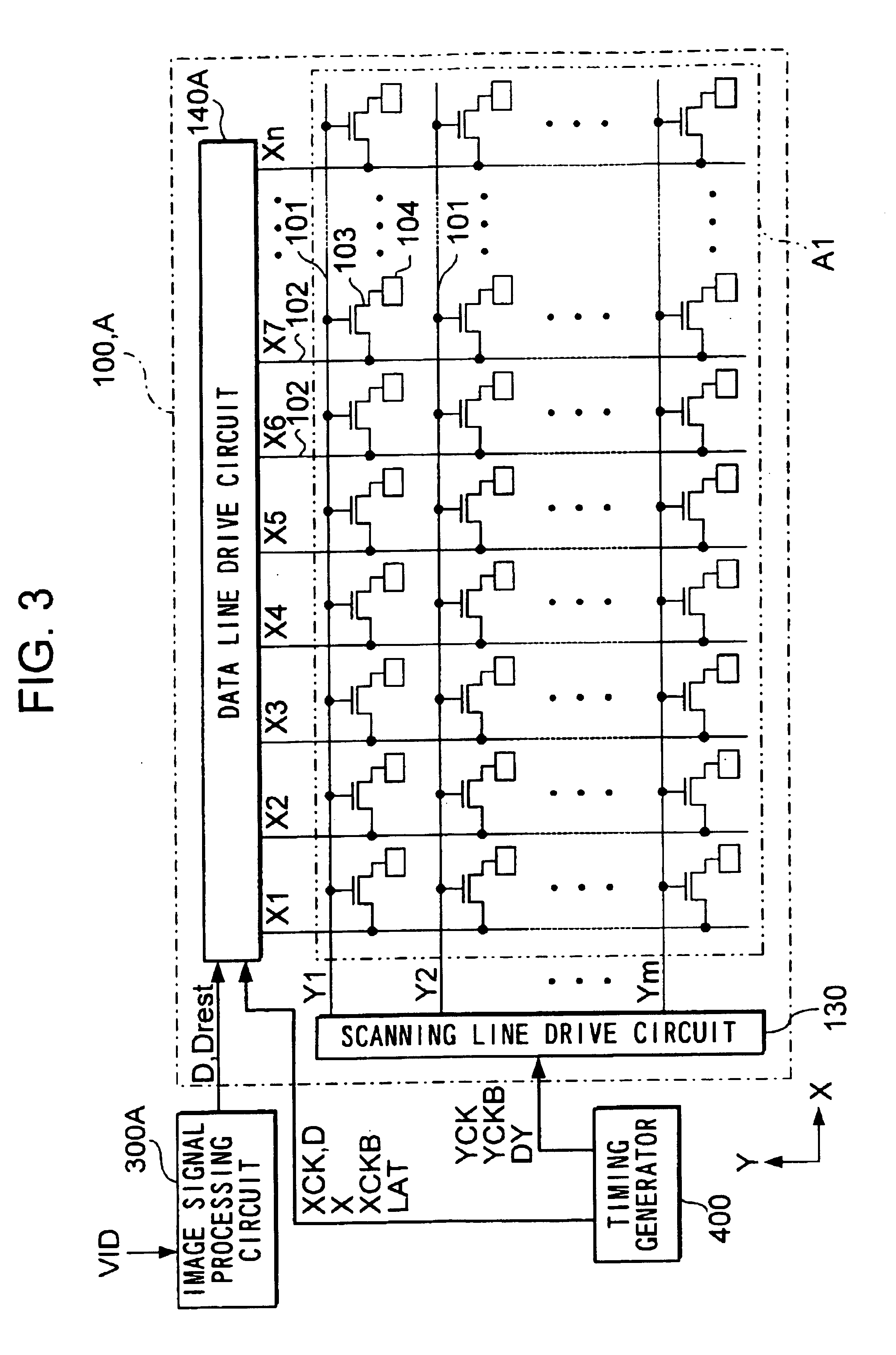
[0063]As shown in FIGS. 1 and 2, an electrophoretic display panel A has an element substrate 100 and an opposing substrate 200. Element substrate 100 is made of glass, a semiconductor or some other suitable material. Opposing substrate 200 is made of glass or some other suitable transparent material. A common electrode 201 is formed on opposing substrate 200. A plurality of pixel electrodes 104 are formed on element substrate 100 to constitute a plurality...

second embodiment

[0143](B) Second Embodiment

[0144]In the above embodiment, rewriting is carried out in a way that after a reset operation as shown in FIG. 16A is carried out, then a writing operation is carried out shown in FIG. 16B to renew a displayed image. In this case, the positions of the pigment particles 3 are initialized in displaying a subsequent image. In the case that dielectric fluid 2 is colored black and the pigment particles 3 are colored white, a black out occurs across the entire image. However, if a change in image is effected sufficiently rapidly, it will not be visible to the naked eye. Nevertheless there is a case that the resetting operation needs a long time according to physical property of the dispersal system 1, which results in the fact that change of the brightness in initializing the pigment particles 3 can be detected.

[0145]In order to deal with the above situation, it is possible that the voltage which corresponds to the difference between the average position to be d...

third embodiment

[0161](C) Third Embodiment

[0162]In the first embodiment, as described before, after the gradation voltage is applied to the pixel electrodes 104 to move the pigment particles 3 by the distance correspondent to the gradation to be displayed, the common voltage Vcom is applied to the pixel electrodes 104 not to apply any electrostatic field to the particles 3. Additionally, the image data D is compensated at the image signal processing circuit 300A before outputting taking the inertia into consideration, in case of small fluid resistance of the dielectric fluid, which means that the particles 3 continue to move under inertia.

[0163]However, it can take a considerable time for pigment particles 3 to become stationary depending on the level of fluid resistance encountered in dielectric fluid 2. In the above example, since pigment particles 3 migrate away from pixel electrodes 104 to the common electrode, if there is little fluid resistance the image displayed will not reach optimum brigh...


PUM


Abstract

A method for driving an active matrix electrophoretic display is provided. In a resetting period Tr, reset data Drest is supplied to a data line drive circuit and a reset voltage is applied to each pixel electrode. Next in a writing period, an image data is supplied to a data line drive circuit and a gradation voltage is applied to each pixel electrode. Subsequently a common voltage is applied to it, in order to take charge which is accumulated between the electrodes away, applying no electric field to a dispersal system. Then a displayed image is held.

Description

[0001]This is a Division of application Ser. No. 09 / 884,092 filed Jun. 20, 2001 now U.S. Pat. No. 6,762,744. The entire disclosure of the prior application is hereby incorporated by reference herein in its entirety.BACKGROUND OF THE INVENTION[0002]1. Technical Field of the Invention[0003]The present invention relates to an electrophoretic display, a method and apparatus for driving it, and an electronic device using it.[0004]2. Description of Related Art[0005]In the conventional art, electrophoretic displays are known which consist of a pair of panels or substrates spaced apart in opposing relation, each of which is provided with an electrode. Between these electrodes a dyed dielectric fluid is provided. Suspended in the fluid are electrically charged particles having a pigment color different to the fluid in which they are suspended (hereinafter referred to simply as pigment particles). In a display update operation, differing voltages are applied via a switching element to the ele...

Claims


Application Information

Patent Timeline
IPC IPC(8): G02F1/01G02F1/167G09G3/34G09G3/20
CPCG02F1/167G09G3/2011G09G3/344G09G2300/08G09G2310/0205G09G2310/027G09G2310/04G09G2310/06G09G2310/061G09G2310/062G09G2320/0276G09G2330/021G09G2340/16G09G2360/18
Inventor KATASE, MAKOTO
Owner E INK CORPORATION
Why Eureka
Try Eureka