Imaging device

Inactive Publication Date: 2005-11-01
OLYMPUS CORP
View PDF9 Cites 32 Cited by
  • Summary
  • Abstract
  • Description
  • Claims
  • Application Information

AI Technical Summary

Benefits of technology

[0018]According to the present invention, it is not necessary to provide a lens moving mechanism such as a motor or a driving circuit by imparting a focusing function and a compensator function, or a focusing function to the deformable reflecting surface, and it i

Problems solved by technology

The mechanical structure for moving these lens units, however, is complicated, and there is the problem that a wide space is necessary for installing this mechanical structure.
The manual method, however, has the problem that it is difficult to provide a lens with a collapsible mount, and the lens may remain in a projecting state when the device is not used, this constituting an obstacle to carrying.
The motor driving method, on the other hand, has problems such as a slow zooming operation, noisy operation and large power consumption.
In addition, it is necessary to provide a mo

Method used


Image

  • Imaging device
  • Imaging device
  • Imaging device

Examples


first embodiment

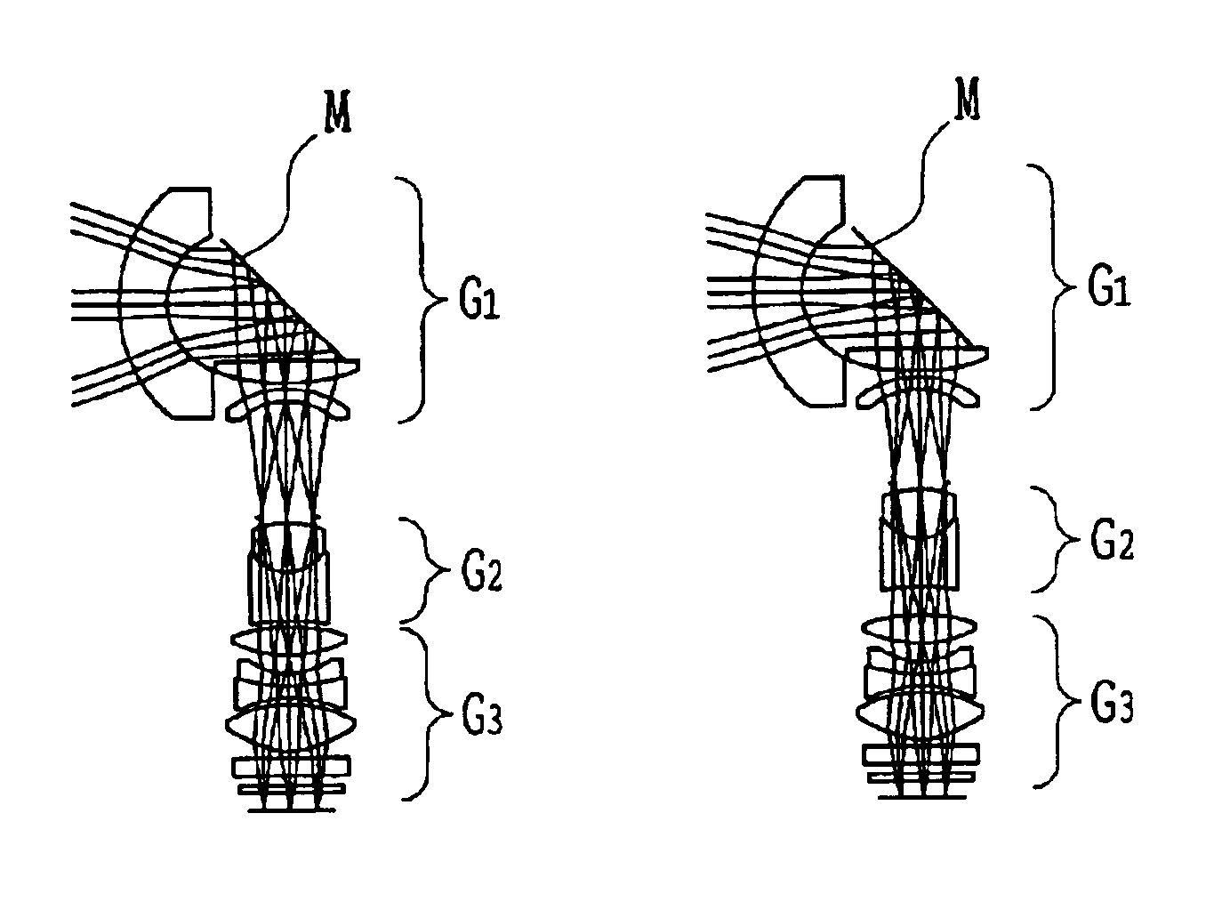
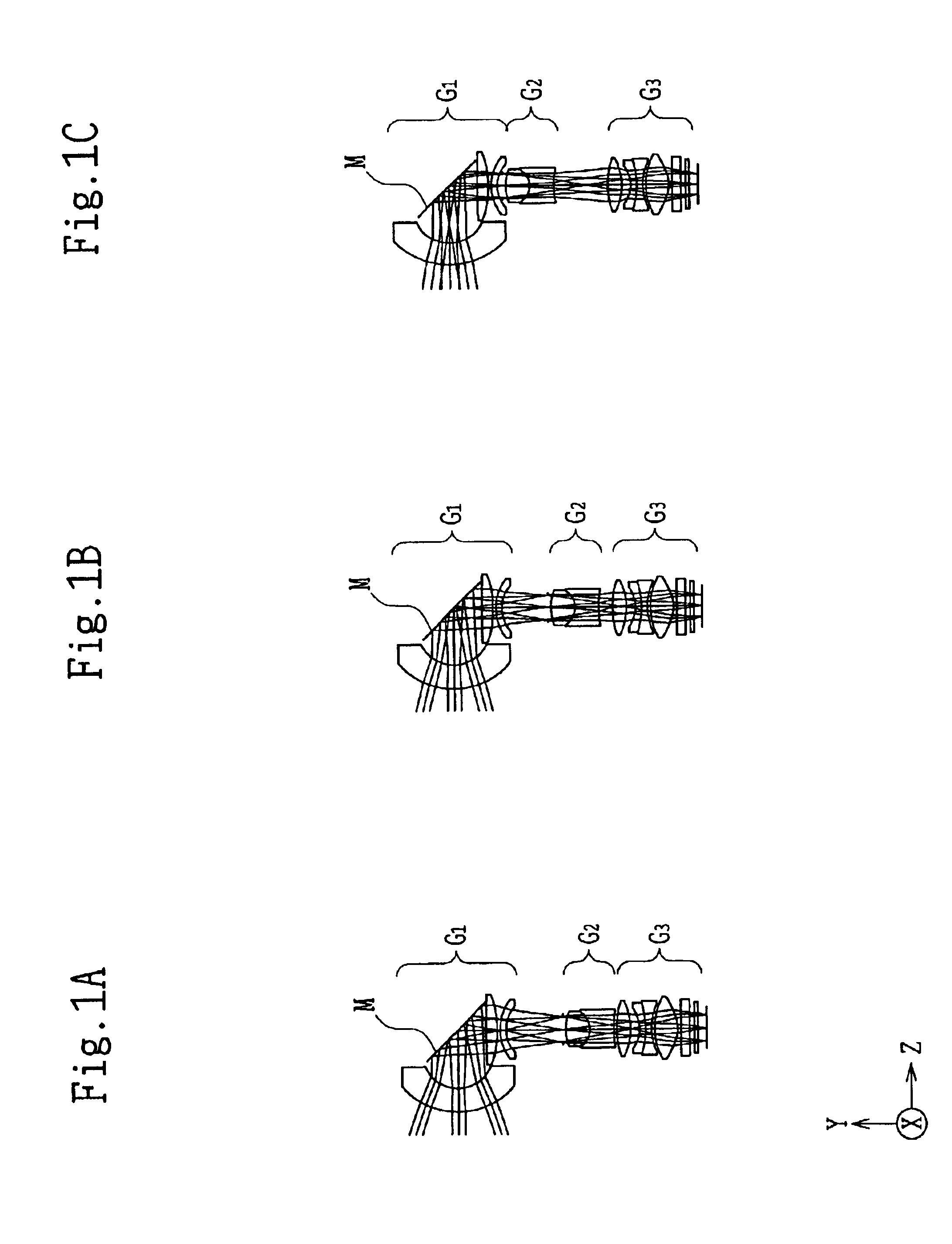
[0131]FIGS. 1A-1C show lens arrangements of a zooming optical system in the first embodiment of the present invention. The zooming optical system of the first embodiment comprises, in order from the object side, a first unit G1 having negative power, a second unit G2 having positive power, and a third unit G3 having positive power. In this configuration, a variable magnification function is imparted by moving the second unit G2, and the resulting focal shift can be corrected via a reflecting surface of a deformable mirror M provided in the first unit G1.

[0132]The design values of the zooming optical system of the first embodiment include a focal length of from 6.0 to 12.0 mm, a released F number of from 2.8 to 3.6 mm, an imaging plane size of from 5.3 mm×4.0 mm, a horizontal view angle at the wide-angle position of 47.66°, a vertical view angle of 36.87°, horizontal view angle at the telephoto position of 24.91°, and a vertical view angle of 28.07°.

[0133]Numerical data and values of...

second embodiment

[0135]FIGS. 8A-8C show lens arrangements of the zooming optical system in the second embodiment of the present invention. The zooming optical system of the second embodiment comprises, in order from the object side, a first unit G1 having negative power, a second unit G2 only with a stop surface, a third unit G3 having positive power, and a fourth unit G4 having positive power. The variable magnification function is imparted by moving the third unit G3, and a focal shift caused thereby can be corrected via the reflecting surface of the deformable mirror M provided in the first unit G1. In the second embodiment, an arrangement is such that a pupil position is shifted to keep a small mirror diameter.

[0136]The design values of the zooming optical system of the second embodiment include a focal length of from 6.0 to 12.0 mm, a release F number of from 2.8 to 4.3 mm, an imaging plane size of 5.3×4.0 mm, a horizontal view angle of 47.66° at the wide-angle position, a vertical view angle o...

third embodiment

[0139]FIGS. 15A-15C show lens arrangements of the zooming optical system in the third embodiment of the present invention. The zooming optical system of the third embodiment comprises, in order from the object side, a first unit G1 having negative power, a second unit G2 having positive power, and a third unit G3 having positive power. The variable magnification function is imparted by moving the second unit G2, and a focal shift caused thereby can be corrected via a reflecting surface of the deformable mirror M provided in the first unit G1. In the third embodiment, a prism P is provided in the first unit G1 to reduce the mirror diameter so that an angle of incidence on the reflecting surface of the deformable mirror M becomes small. It is desirable that the angle of incidence is 55° or smaller, preferably 40° or smaller.

[0140]The design values of the zooming optical system of the third embodiment include a focal length of from 6.0 to 12.0 mm, a release F number of from 2.8 to 3.8 ...


PUM


Abstract

A zooming optical system has at least one lens unit having a variable magnification function and at least one deformable reflecting surface having a compensator or focusing function. In this case, the zooming optical system satisfies the following conditions: 0≦|øx/φ|<0.5, 0≦|øy/φ|<0.5, where øx is power of an axis perpendicular to a direction of decentering of the deformable reflecting surface; øy is power of an axis in parallel with a direction of decentering of the deformable reflecting surface; and φ is power of the entire optical system.

Description

BACKGROUND OF THE INVENTION[0001]1. Field of the Invention[0002]The present invention relates to an imaging device, and in particular, to an electronic imaging device having a zooming optical system.[0003]2. Description of Related Art[0004]A zooming optical system comprises lens units: a unit varying the focal length (a variator), a unit compensating for the shift of an image surface and aberration resulting therefrom (a compensator), a unit focusing an object, and a fixed unit correcting aberration characteristics.[0005]The zooming optical system is constructed so that the magnification change and focal adjustment thereof are performed by moving a predetermined lens unit, of the above-mentioned lens units, in the coaxial direction.[0006]The mechanical structure for moving these lens units, however, is complicated, and there is the problem that a wide space is necessary for installing this mechanical structure.[0007]Available methods for moving the lens units of a zooming optical sy...

Claims


Application Information

Patent Timeline
IPC IPC(8): G02B15/14G02B26/08G02B17/08G02B13/00G02B5/10G02B7/10G02B13/18G02B15/16G03B5/00
CPCG02B15/177G02B17/0896G02B26/0825G02B15/143507G02B15/144515
Inventor AMANAI, TAKAHIRO
Owner OLYMPUS CORP
Why Eureka
Try Eureka