Micromirror elements, package for the micromirror elements, and projection system therefor
What is Al technical title?
Al technical title is built by PatSnap Al team. It summarizes the technical point description of the patent document.
a technology of micromirror elements and projection systems, applied in television systems, instruments, non-linear optics, etc., can solve problems such as light leakage into, and achieve the effects of reducing the contrast ratio of the micromirror, minimizing light diffraction, and minimizing the cost of illumination optics
Inactive Publication Date: 2005-11-08
VENTURE LENDING & LEASING IV +1
View PDF109 Cites 70 Cited by
Summary
Abstract
Description
Claims
Application Information
AI Technical Summary
This helps you quickly interpret patents by identifying the three key elements:
Problems solved by technology
Method used
Benefits of technology
[0009]In order to minimize light diffraction along the direction of switching and in particular light diffraction into the acceptance cone of the collection optics, in the present invention, micromirrors are provided which are not rectangular (“rectangular” as used herein including square micromirrors). Diffraction as referred to herein, denotes the scattering of light off of a periodic structure, where the light is not necessarily monochromatic or phase coherent. Also, in order to minimize the cost of the illumination optics and the size of the display unit of the present invention, the light source is pla
Problems solved by technology
Orthogonal sides cause incident light to diffract along the direction of micromirror switching,
Method used
Image
Click on the blue label to locate the original text in one second.
Reading with bidirectional positioning of images and text.
Examples
Embodiment Construction
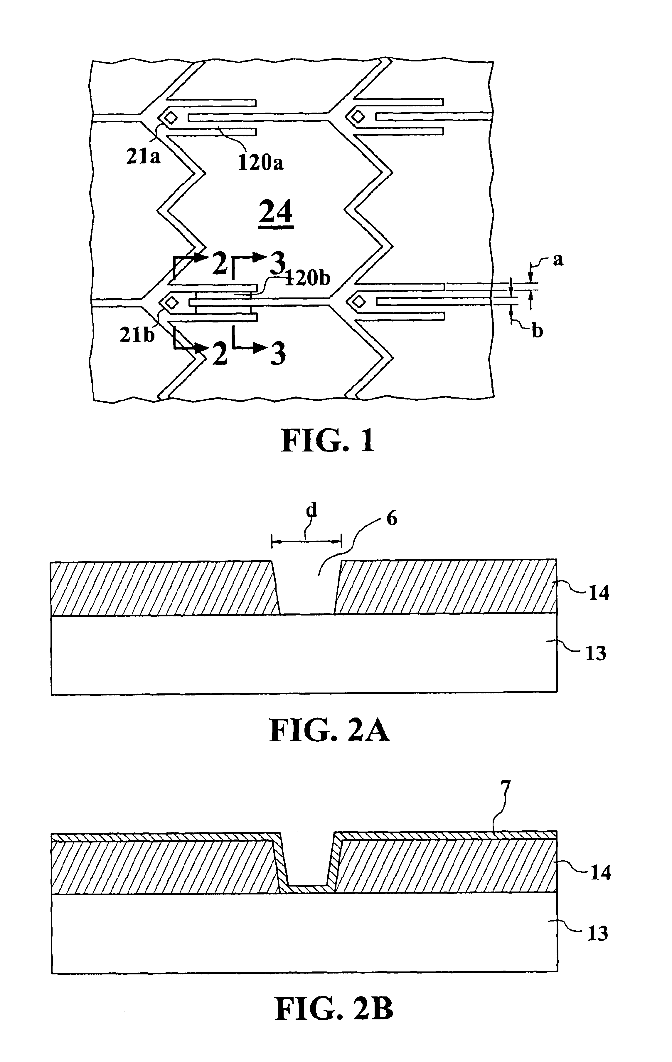
[0068]Processes for microfabricating a movable micromirror or micromirror array are disclosed in U.S. Pat. Nos. 5,835,256 and 6,046,840 both to Huibers, the subject matter of each being incorporated herein by reference. A similar process for forming the micromirrors of the present invention is illustrated in FIGS. 1 to 3. FIG. 1 is a top view of one embodiment of the micromirrors of the present invention. As can be seen in FIG. 1, posts 21a and 21b hold micromirror plate 24 via hinges 120a and 120b above a lower substrate having electrodes thereon (not shown) for causing deflection of micromirror plate 24. Though not shown in FIG. 1, and as will be discussed further herein, thousands or even millions of micromirrors 24 can be provided in an array for reflecting light incident thereon and projecting an image to a viewer or target / screen.
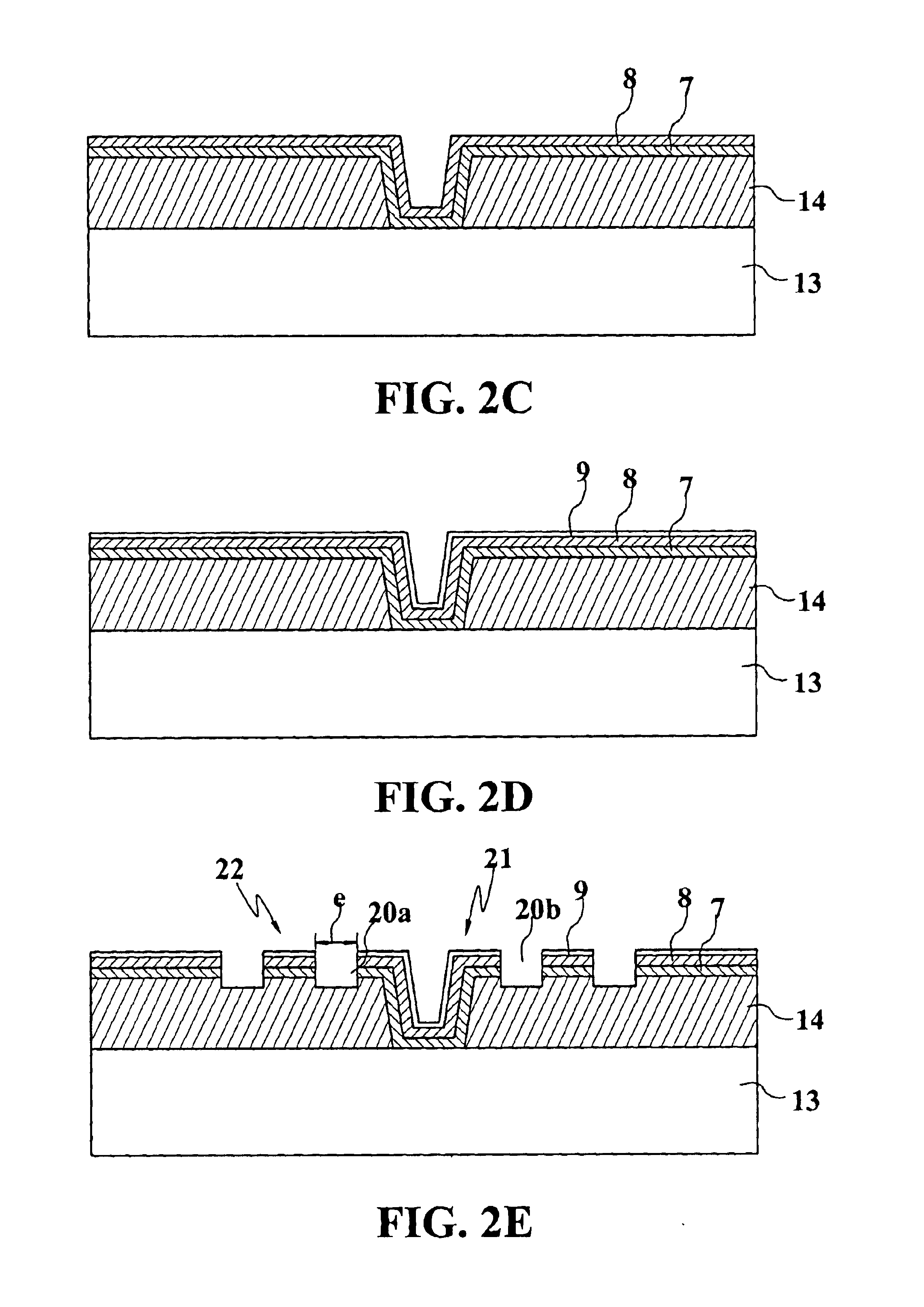
[0069]Micromirror 24, and the other micromirrors in the array, can be fabricated by many different methods. One method is illustrated in FIGS. 2A to ...
PUM
Abstract
In order to minimize light diffraction along the direction of switching and more particularly light diffraction into the acceptance cone of the collection optics, in the present invention, micromirrors are provided which are not rectangular. Also, in order to minimize the cost of the illumination optics and the size of the display unit of the present invention, the light source is placed orthogonal to the rows (or columns) of the array, and/or the light source is placed orthogonal to a side of the frame defining the active area of the array. The incident light beam, though orthogonal to the sides of the active area, is not however, orthogonal to any substantial portion of sides of the individual micromirrors in the array. Orthogonal sides cause incident light to diffract along the direction of micromirror switching, and result in light ‘leakage’ into the ‘on’ state even if the micromirror is in the ‘off’ state. This light diffraction decreases the contrast ratio of the micromirror. The micromirrors of the present invention result in an improved contrast ratio, and the arrangement of the light source to micromirror array in the present invention results in a more compact system. Another feature of the invention is the ability of the micromirrors to pivot in opposite direction to on and off positions (the on position directing light to collection optics), where the movement to the on position is greater than movement to the off position. A further feature of the invention is a package for the micromirror array, the package having a window that is not parallel to the substrate upon which the micromirrors are formed. One example of the invention includes all the above features.
Description
[0001]This application is a 371 of PCT / US01 / 24332 filed Aug. 3, 2001,[0002]which is a CIP of Ser. No. 09 / 631,536, filed Aug. 3, 2000, now U.S. Pat. No. 6,529,310,[0003]which is a CIP of Ser. No. 09 / 437,586, filed Nov. 9, 1999, now U,S. Pat. No. 6,172,797,[0004]which is a continuation of Ser. No. 09 / 160,361, filed Sep. 24, 1998, now U.S. Pat. No. 6,046,840,[0005]and said PCT / US01 / 24332 filed Aug. 3, 2000 claims benefit of Ser. No. 60 / 229,246, filed Aug. 30, 2000,[0006]and is a CIP of Ser. No. 09 / 732,445, filed Dec. 7, 2000, now U.S. Pat. No. 6,523,961,[0007]which claims benefit of Ser. No. 60 / 229,246, filed Aug. 30. 2000.BACKGROUND[0008]The present invention relates to movable micromirrors and micromirror arrays for, e.g., projection displays. U.S. Pat. Nos. 5,835,256 and 6,046,840 to Huibers, and U.S. patent application Ser. No. 09 / 617,419 to Huibers et al., the subject matter of each being incorporated herein by reference, disclose micro-electromechanical devices (MEMS) for steerin...
Claims
Application Information
Patent Timeline
Application Date:The date an application was filed.
Publication Date:The date a patent or application was officially published.
First Publication Date:The earliest publication date of a patent with the same application number.
Issue Date:Publication date of the patent grant document.
PCT Entry Date:The Entry date of PCT National Phase.
Estimated Expiry Date:The statutory expiry date of a patent right according to the Patent Law, and it is the longest term of protection that the patent right can achieve without the termination of the patent right due to other reasons(Term extension factor has been taken into account ).
Invalid Date:Actual expiry date is based on effective date or publication date of legal transaction data of invalid patent.