Induction heating of a workpiece

a workpiece and induction heating technology, applied in the direction of induction heating, induction current sources, electric/magnetic/electromagnetic heating, etc., can solve the problems of high frequency power supply, inability to achieve uniform cross sectional heating of the strip, and inability to laterally move the continuous strip out from within the coil, etc., to achieve the effect of providing low frequency ac curren

Inactive Publication Date: 2005-11-08
INDUCTOTHERM INDS
View PDF5 Cites 35 Cited by
  • Summary
  • Abstract
  • Description
  • Claims
  • Application Information

AI Technical Summary

Benefits of technology

[0009]In another aspect, the present invention is an apparatus for, and method of, inductively heating a strip moving through an induction coil assembly wherein the induction coil assembly comprises upper and lower coil sections through which the strip moves (see e.g. FIG. 2). AC current is supplied to the upper and lower coil sections by two high frequency inverters and one low frequency inverter that are connected to the upper and lower coil sections by a network of inductive and capacitive circuit elements (see e.g. FIG. 3). The high frequency inverters are arranged to supply a high frequency ac current to the induction coil assembly to create a longitudinal flux magnetic field that inductively heats the strip uniformly across its cro

Problems solved by technology

However, when a longitudinal flux inductor is used to inductively heat a thin strip, a high frequency power supply, with attendant cost penalty, is required.
Further the solenoidal configuration of a conventional longitudinal flux inductor makes it impossible to laterally move the continuous strip out from within the coil as may be desired, for example, to replace the ex

Method used


Image

  • Induction heating of a workpiece
  • Induction heating of a workpiece
  • Induction heating of a workpiece

Examples


Embodiment Construction

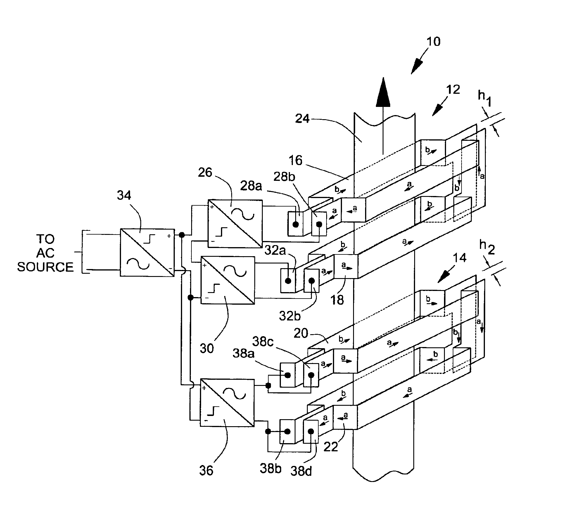
[0015]Referring now to the drawings, wherein like numerals indicate like elements, there is shown in the FIG. 1, one example of the induction heating coil assembly 10 of the present invention. Induction heating coil assembly 10 comprises first coil assembly 12 and second coil assembly 14. First coil subassembly 12 comprises upper coil section 16 and lower coil section 18 as disclosed in U.S. Pat. No. 5,837,976, which is incorporated herein in its entirety. Gap h1 separates first coil assembly 12 into two parts and allows workpiece 24 to be laterally removed from within the coil. A non-limiting configuration of the workpiece is an electrically conductive strip. Second coil assembly 14 comprises a first coil 20 and second coil 22 which form a coil pair on opposing sides of workpiece 24. Gap h2 separates the first and second coils and allows the strip to be laterally removed from within the pair of coils. In this non-limiting example, the strip moves sequentially through the second coi...


PUM


Abstract

An apparatus and process are provided for controlling the cross sectional temperature profile of a continuously moving workpiece with an induction coil assembly that provides for a combination of longitudinal and transverse magnetic flux field heating of the workpiece. The induction coil assembly includes means for laterally moving the workpiece in and out of the coil assembly without movement of the coil assembly.

Description

CROSS REFERENCE TO RELATED APPLICATIONS[0001]This application claims the benefit of U.S. Provisional Application No. 60 / 469,539 filed May 9, 2003, hereby incorporated herein by reference.FIELD OF THE INVENTION[0002]The present invention generally relates to magnetic induction heating of a workpiece, and in particular, to induction heating of a workpiece moving through an induction heating coil assembly.BACKGROUND OF THE INVENTION[0003]The induction coil through which a moving workpiece is heated by magnetic induction is typically configured as a longitudinal flux inductor or transverse flux inductor. The workpiece may be a continuous, electrically conductive strip that passes through the induction coil. A longitudinal flux inductor is generally described as a solenoidal coil that surrounds the strip. AC current flowing through the solenoidal coil produces a magnetic field that is parallel with the longitudinal axis of the strip in regions where the field penetrates the strip. The ma...

Claims


Application Information

Patent Timeline
IPC IPC(8): H05B6/40H05B6/10H05B6/36H05B6/02
CPCH05B6/104H05B6/365
Inventor PEYSAKHOVICH, VITALY A.LOVENS, JEANFONTAINE, MICHELDICKSON, PETER ROBERT
Owner INDUCTOTHERM INDS
Why Eureka
Try Eureka