

Organic EL display device having certain relationships among constituent element refractive indices
- Summary
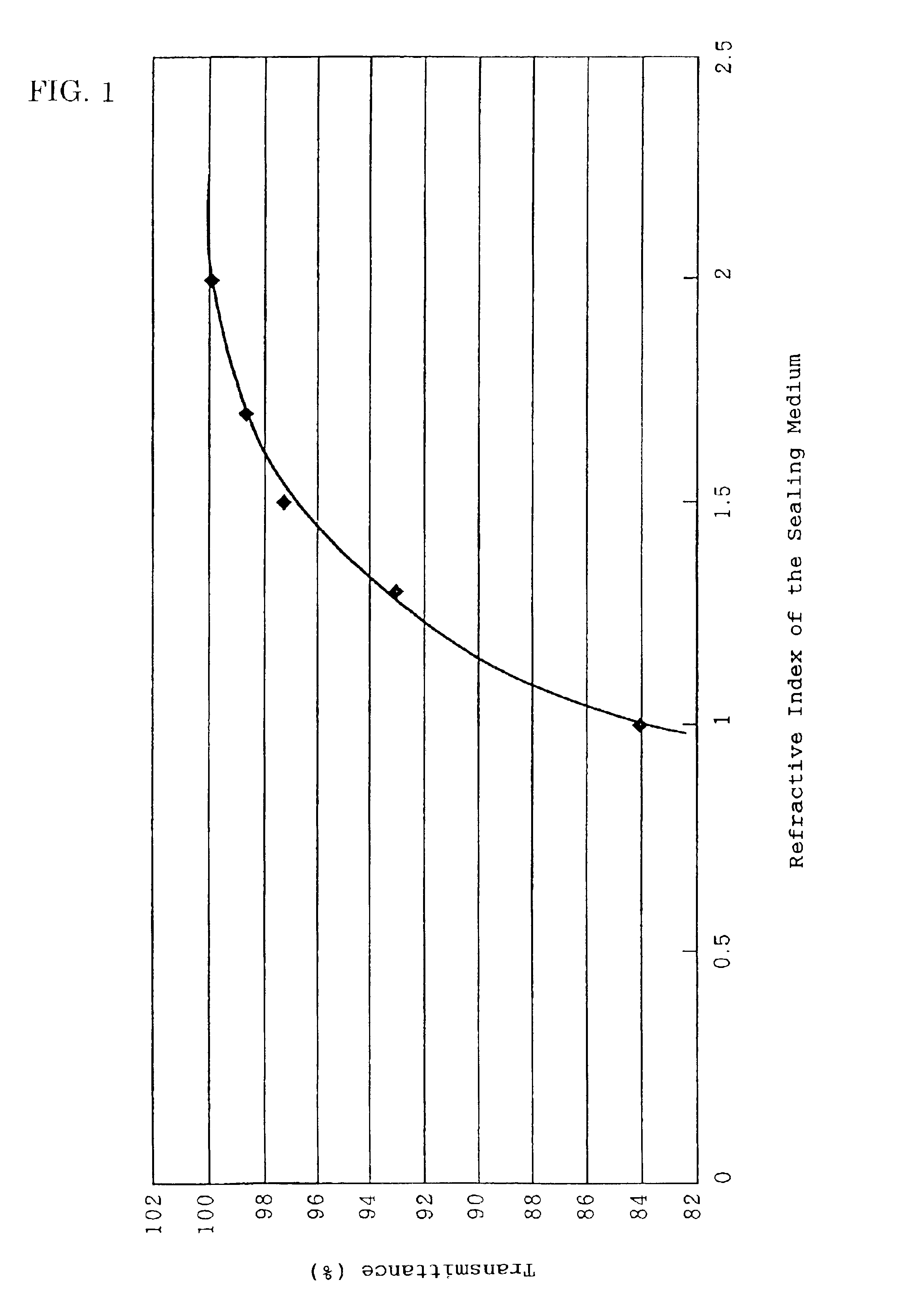
- Abstract
- Description
- Claims
- Application Information
AI Technical Summary
Benefits of technology
Problems solved by technology
Method used
Image

Examples
first embodiment
[First Embodiment]
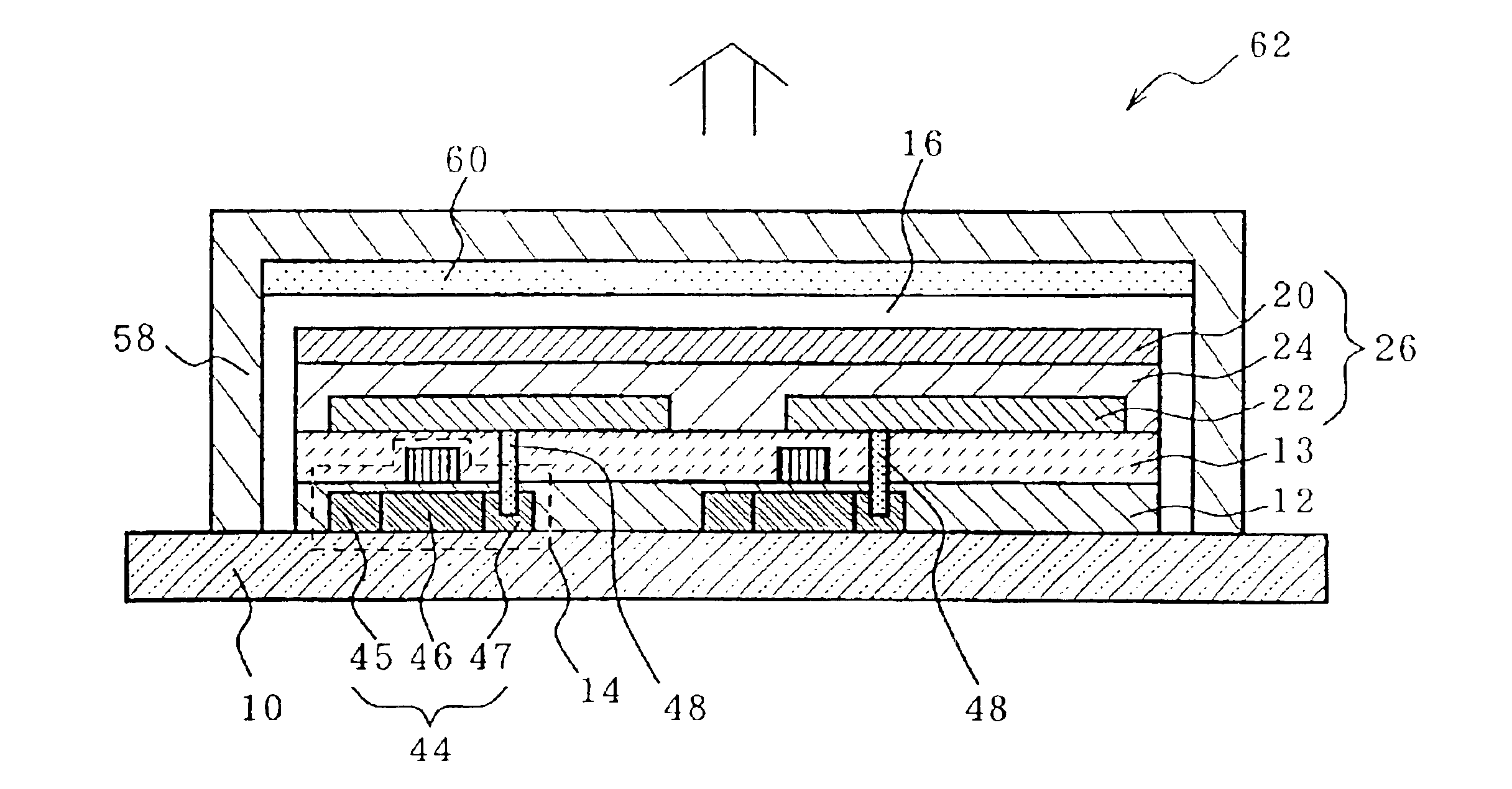
[0065]As illustrated in FIG. 2, the first embodiment is specifically an active matrix type organic EL display device 62 wherein TFTs 14 embedded in an electrically insulator (including a gate insulating film) 12, an inter-insulator (flattening film) 13, organic EL elements 26 and contact holes (electrically connecting members) 48 for connecting the TFTs 14 and the organic EL elements 26 electrically are disposed on a supporting substrate (which may be referred to only as a substrate) 10. The device 62 further comprises a sealing medium 16, a color changing medium 60 and a sealing member 58.
[0066]The refractive index of an upper electrode 20 in the organic EL element 26, that of the sealing medium 16 and that of the sealing member 58 are represented by n1, n2 and n3, respectively. In this case, the following expression (1) is satisfied in the active matrix type organic EL display device 62.
n1≦n2≦n3 (1)
[0067]The following will describe the constituent elements and s...
second embodiment
[Second Embodiment]
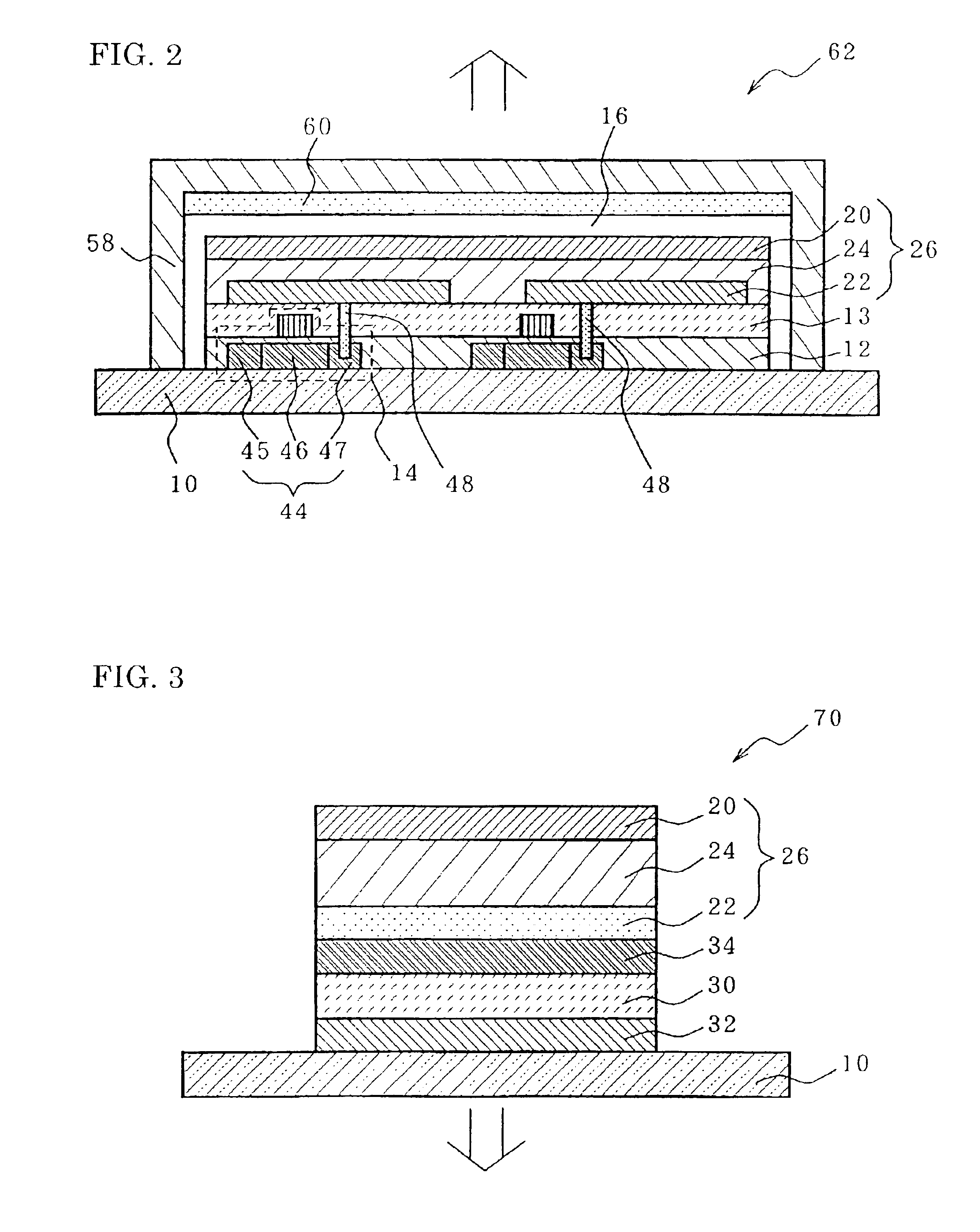
[0199]As is roughly illustrated in FIG. 3, an organic EL display device 70 of the second embodiment is an organic EL display device having the following characteristics: the device 70 comprises, on a supporting substrate 10, third color changing medium 30 and 32, a transparent resin layer (which may be referred to as a first transparent resin layer) 34, and an organic EL element 26 made of an organic luminescent medium 24 sandwiched between a lower electrode 22 and an upper electrode 20; EL emission is taken out from the side of the lower electrode 22; and the device 70 satisfies the following expression (5)″ when the refractive index of the lower electrode 22 is represented by n5, those of the third color changing medium 30 and 32 are represented by n6(1) and n6(2), respectively, and that of the supporting substrate 10 is represented by n8.
[0200]As illustrated in FIG. 3, the organic EL display device 70 of the second embodiment preferably has the first transparen...
third embodiment
[Third Embodiment]
[0244]An organic EL display device of the third embodiment is as is illustrated in FIG. 8 an organic EL display device having the following characteristics: the device comprises a color changing medium (which may be referred to as a fourth color changing medium), a supporting substrate, a transparent resin layer (which may be referred to as a third transparent resin layer), a lower electrode, an organic luminescent medium and an upper electrode successively from the lower side thereof; EL emission is taken out through the fourth color changing medium from the side of the lower electrode; and the device satisfies the following expression (9) when the refractive index of the lower electrode is represented by n5, that of the fourth color changing medium is represented by n9, and that of the supporting substrate is represented by n8:
n5≦n8≦n9 (9)
[0245]The following will describe a characteristic relationship between the refractive indexes of the respective layers, and ...
PUM
| Property | Measurement | Unit |
|---|---|---|
| Electrical conductance | aaaaa | aaaaa |
| Electrical conductance | aaaaa | aaaaa |
| Transparency | aaaaa | aaaaa |
Abstract
Description
Claims
Application Information