Eureka AIR delivers breakthrough ideas for toughest innovation challenges, trusted by R&D personnel around the world.

Laser counter-measure using fourier transform imaging spectrometers

a technology of imaging spectrometer and countermeasure, applied in the field of countermeasures, using a fourier transform imaging spectrometer, can solve the problems of saturation artifacts, image artifacts of different levels, and achieve the effect of reducing the level of interfering signals

Active Publication Date: 2005-11-08
HARRIS CORP
View PDF19 Cites 36 Cited by
  • Summary
  • Abstract
  • Description
  • Claims
  • Application Information

AI Technical Summary

Benefits of technology

[0005]To meet this and other needs, and in view of its purposes, the present invention provides a system for imaging an object of interest. The system includes an optical detector for providing an output signal, in response to detecting the object of interest; a spectrometer, disposed between the object of interest and the optical detector for providing interferograms of the object of interest to the optical detector; and a processor for processing the output signal from the optical detector. The spectrometer is configured to provide interferograms of an interfering signal, and the processor is configured to reduce a level of the interfering signal, based on the interferograms of the interfering signal and the object of interest

Problems solved by technology

Laser energy incident upon an imaging system leads to various levels of image artifacts, up to and including complete blanking or washout of the collected image.
In addition, the high intensity of the laser energy incident upon the focal plane may lead to saturation artifacts, such as blooming or bleeding in the detection device.
The laser radiation may be scattered across the focal plane array, leading to a saturated image and an inability of the imager to distinguish between the target and features of the target.

Method used


Image

  • Laser counter-measure using fourier transform imaging spectrometers
  • Laser counter-measure using fourier transform imaging spectrometers
  • Laser counter-measure using fourier transform imaging spectrometers

Examples


Embodiment Construction

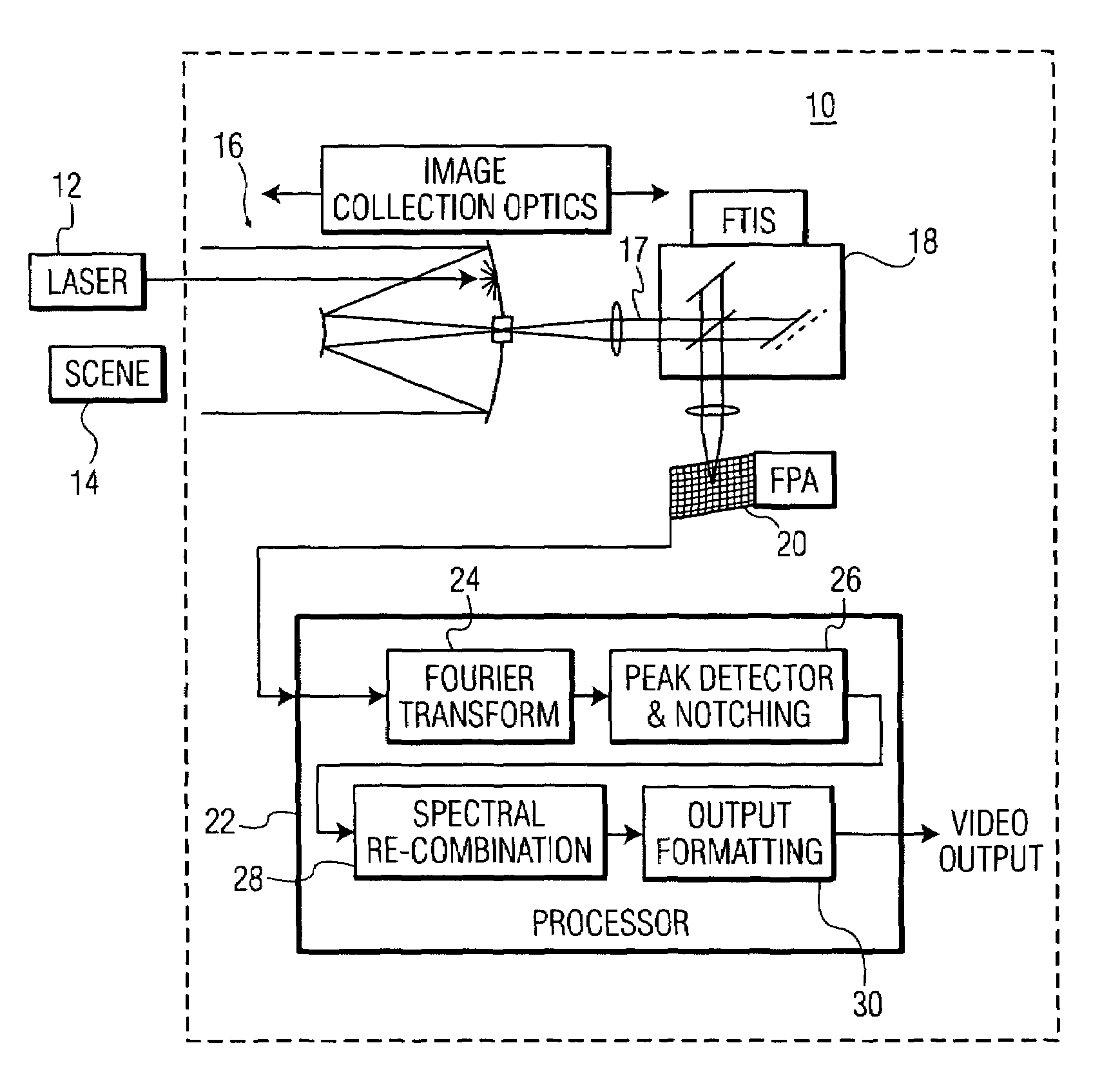
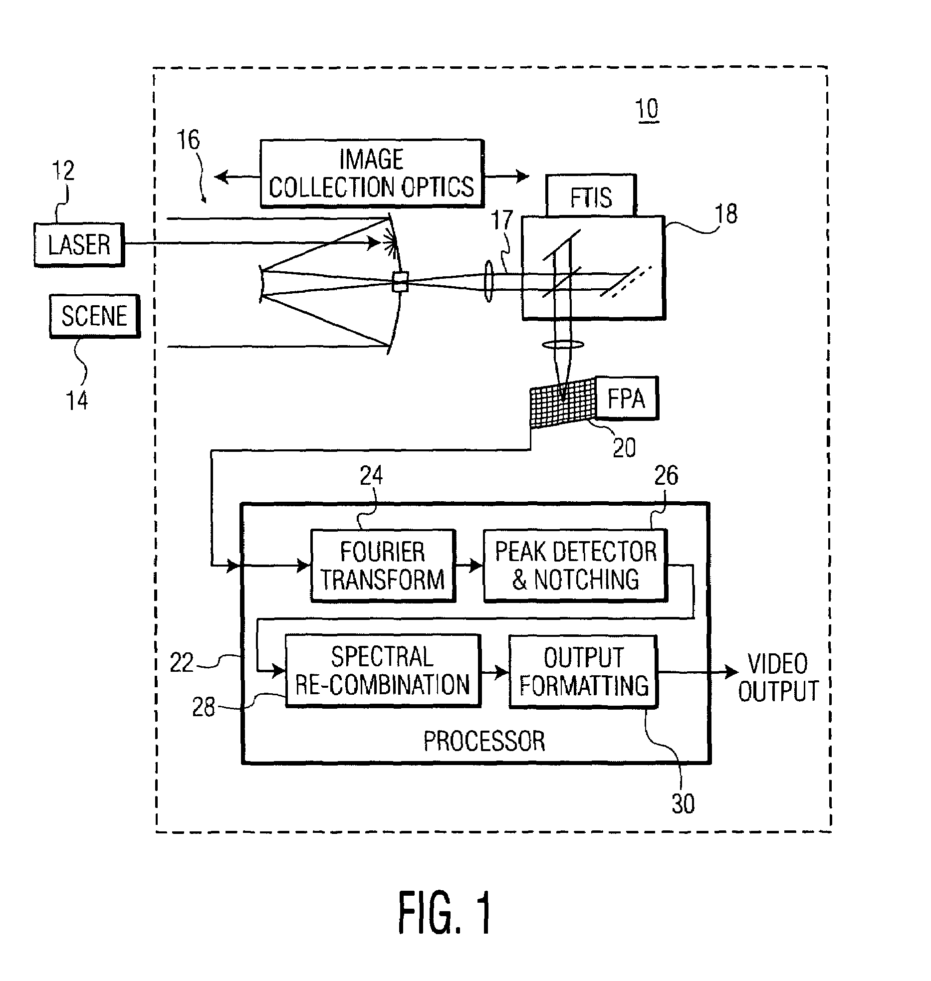
[0028]Referring to FIG. 1, there is shown an imaging system for reducing or eliminating interference from unwanted laser illumination into the imaging system, the system generally designated as 10. Imaging system 10 includes image collection optics 16, Fourier transform imaging spectrometer (FTIS) 18, focal plane array (FPA) 20 and processor 22.

[0029]Light from a target of interest, for example light from scene 14, is directed toward the image collection optics, which may include a telescopic lens and a collimator lens. Collimated beam 17, formed by the collimator lens, is then directed into FTIS 18. As will be explained, FTIS 18 converts the incoming scene energy into interferograms, at each point of the imaging field. These interferograms, which are representations of the output spectrum of the image, at each point of the imaging field, are directed to a two-dimensional array detector, for example FPA 20.

[0030]Since the interferograms represent a Fourier transform of the spectral ...


PUM


Abstract

In an imaging system providing an image of a target of interest, a method of reducing interference from a laser beam includes the steps of: (a) receiving optical energy from the target of interest and the laser beam; (b) forming an interferogram of spectral energy, at each spatial position of an image, based on the optical energy received in step (a); (c) detecting the interferogram of spectral energy, at each of the spatial positions, to provide a corresponding spectral band of intensity values; (d) selecting an intensity level in the spectral band, detected in step (c), that is greater than a predetermined value, and reducing the selected intensity level; and (e) forming an image of the target of interest, after reducing the selected intensity level of step (d).

Description

FIELD OF THE INVENTION[0001]The present invention relates, in general, to a system and method for reducing interference from unwanted laser radiation into an imager. More specifically, the present invention relates to counter-measures, using a Fourier transform spectrometer, to prevent a CW laser beam or a pulsed laser beam from saturating an imager, or any optical collection system.BACKGROUND OF THE INVENTION[0002]Laser energy incident upon an imaging system leads to various levels of image artifacts, up to and including complete blanking or washout of the collected image. This is due to laser energy scattered off optical surfaces and spread across the detecting focal plane of the imager. In addition, the high intensity of the laser energy incident upon the focal plane may lead to saturation artifacts, such as blooming or bleeding in the detection device.[0003]In an exemplary scenario, an imager disposed in an aircraft may be is collecting radiation and providing video images of a ...

Claims


Application Information

Patent Timeline
IPC IPC(8): G01B9/02G01J3/28G01J3/453G01S7/495
CPCG01J3/2823G01J3/453G01S7/495
Inventor WHEEL, PETER J.WOODY, LOREN M.
Owner HARRIS CORP
Why Eureka
Eureka Blog
Learn More