Servo detection control system, servo detection control method and hard disk drive
a control system and servo technology, applied in the direction of maintaining head carrier alignment, recording signal processing, instruments, etc., can solve problems such as format loss and narrow data recording area
- Summary
- Abstract
- Description
- Claims
- Application Information
AI Technical Summary
Problems solved by technology
Method used
Image
Examples
first embodiment
[0078]A notebook PC is apt to suffer from a strong shock at its main body as a result of its fall and rough handling because of its usage pattern. Because of it, as shown in FIG. 17, there is also a phenomenon that a fixed position of a built-in disk to a spindle deviates (in FIG. 17, for convenience of explanation, it is illustrated so that a head deviates). This is caused by a slip in a circumference direction, which mainly results from weakened fixed torque of the disk for a very short period of time. As is the case with the first embodiment described above, if there are a plurality of built-in disks, the slip of the disk causes the servo signal area 13 to deviate between disks (heads), which interferes with servo detection. In addition, even if the number of disks is one, if a suspension, on which a head is mounted, is bent by a strong shock, a head position relatively deviates between disk surfaces, causing skew in a circumference direction, and in a track width direction, of t...
second embodiment
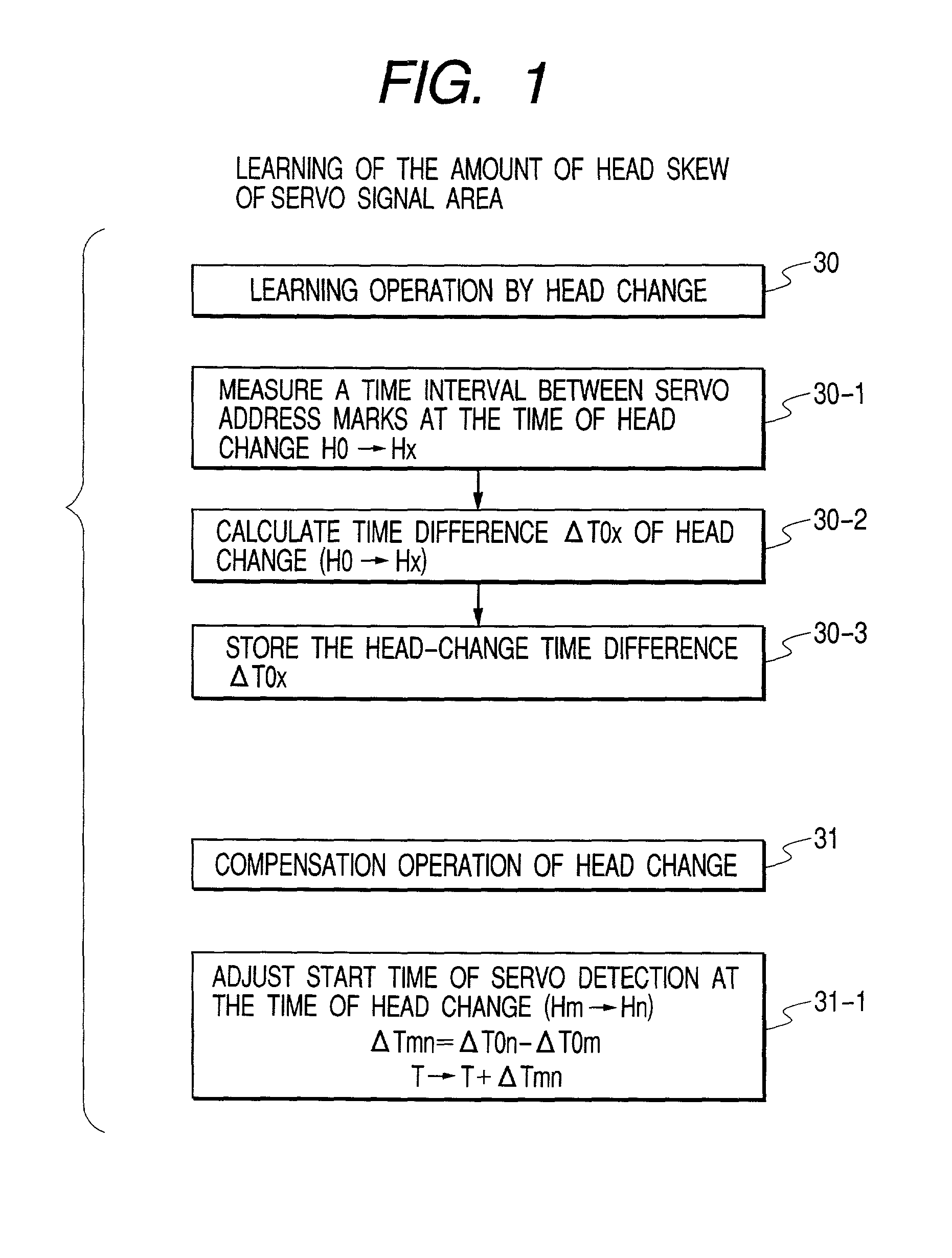
[0093]As shown in FIG. 7, if one pre-STW disk by the media prewrite STW of (1) is built into (both sides are used), the amount of head skew (ΔT0x, ΔD0x) is determined by an error of mounted positions between a head for recording a servo signal of STW and a head on the hard disk drive with reference to a center of a disk mounted position. Because the skew occurs in a servo signal area with a length approximately from several tens to one hundred and several tens of μm, applying the same technique as the second embodiment described above to between sides of the disk can cope with it.
[0094]However, if a plurality of pre-STW disks by media prewrite STW of (1) are built into, or if one or a plurality of patterned disk STWs of (2) is built into, or if one or a plurality of pre-STW disks by magnetic printed media STW (both sides are uses) is built into, it is necessary to cope with timing skew of several servo sectors in a servo signal area between heads.
third embodiment
[0095]Next, servo detection control relating to a hard disk according to the present invention will be described as below. This embodiment relates to the followings: as shown in FIG. 8, a case where a plurality of pre-STW disks by a media prewrite STW are built into; as shown in FIG. 18, a case where one pre-STW disk by a patterned disk STW and a magnetic printed media STW (STW are applied to both sides) are built into; and as shown in FIG. 9, a case a plurality of pre-STW disks by the patterned disk STW and the magnetic printed media STW are built into.
[0096]Applying the media STW technique described above to the STW device enables us to reduce a STW cost per disk to a large extent. In addition to it, high quality of a servo signal can also be expected by making a dedicated device.
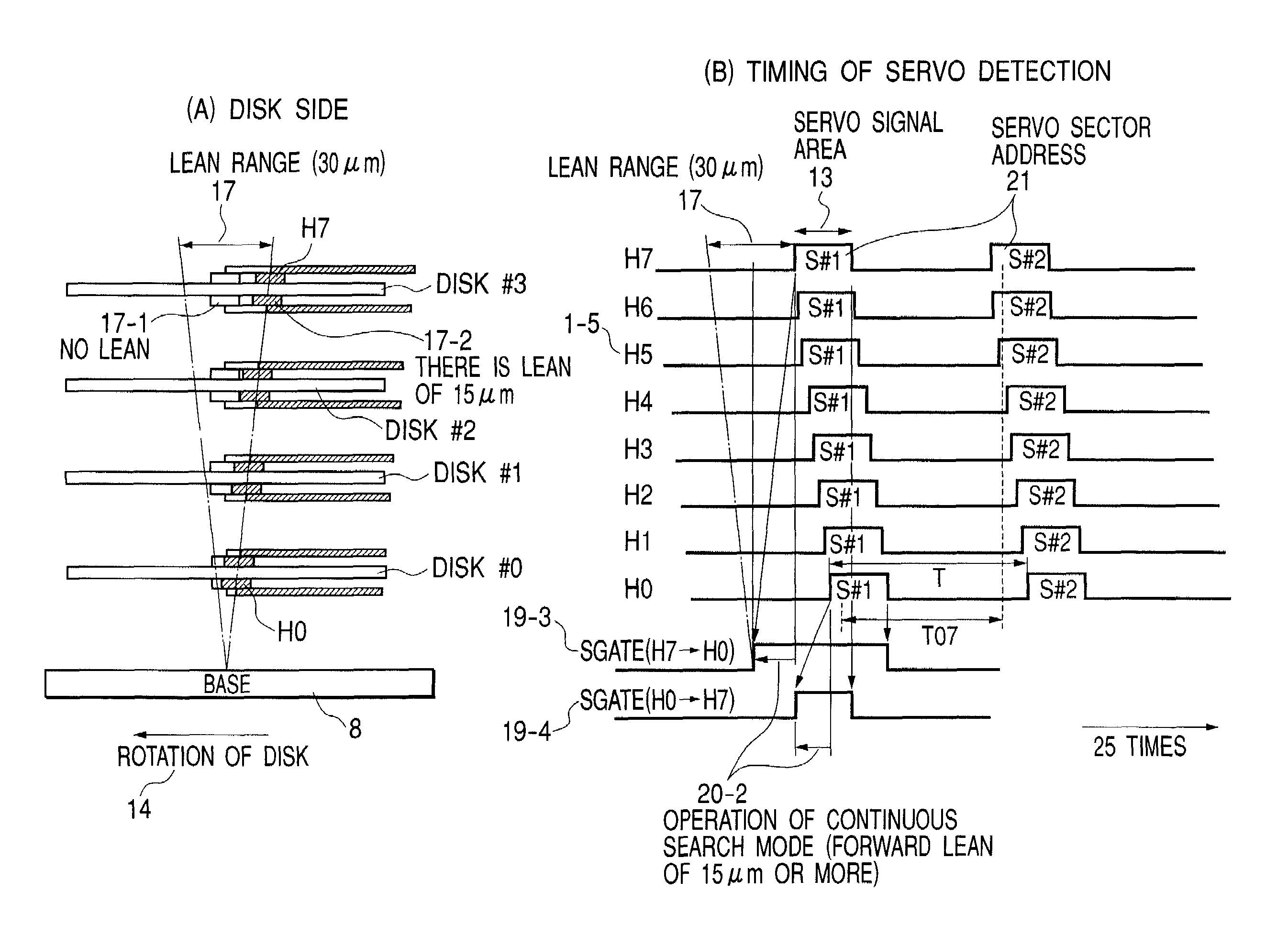
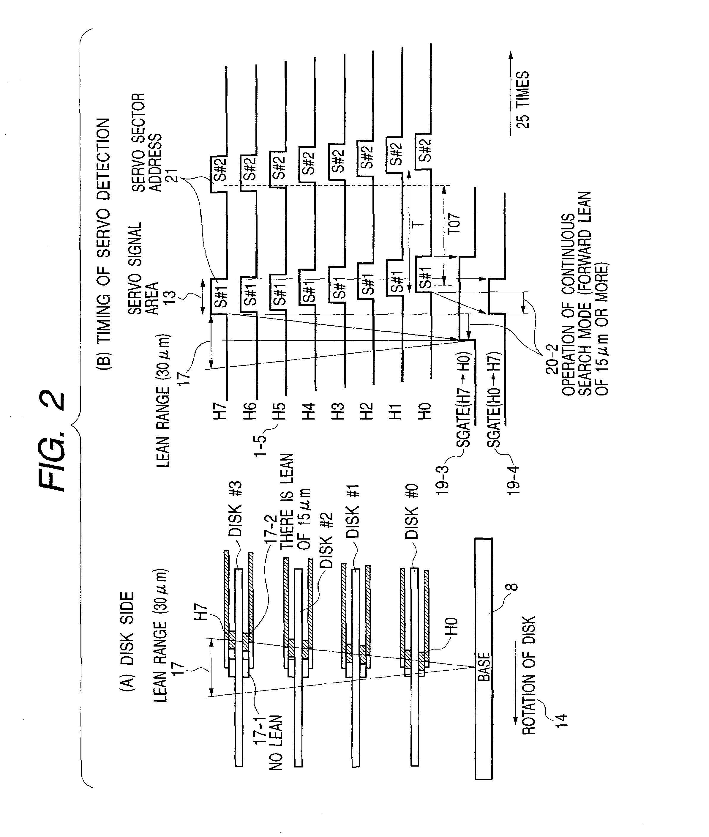
[0097]In this embodiment, in order to cope with skew of a servo signal area between large heads extending over several servo sectors, the following configuration is adopted.
[0098]In this embodiment, besid...
PUM
| Property | Measurement | Unit |
|---|---|---|
| width | aaaaa | aaaaa |
| width | aaaaa | aaaaa |
| length | aaaaa | aaaaa |
Abstract
Description
Claims
Application Information
 - R&D
- Intellectual Property
- Life Sciences
- Materials
- Tech Scout
- Unparalleled Data Quality
- Higher Quality Content
- 60% Fewer Hallucinations
Browse by: Latest US Patents, China's latest patents, Technical Efficacy Thesaurus, Application Domain, Technology Topic, Popular Technical Reports.
© 2025 PatSnap. All rights reserved.Legal|Privacy policy|Modern Slavery Act Transparency Statement|Sitemap|About US| Contact US: help@patsnap.com


