Voltage converter with a self-oscillating control circuit

a technology of voltage converter and control circuit, which is applied in the direction of ac-dc conversion, electric variable regulation, instruments, etc., can solve the problems of crippling disadvantage, increasing cost, and reducing the service life of the converter

Inactive Publication Date: 2005-11-08
STMICROELECTRONICS SRL
View PDF5 Cites 60 Cited by
  • Summary
  • Abstract
  • Description
  • Claims
  • Application Information

AI Technical Summary

Benefits of technology

[0017]The present invention aims at providing a novel converter of switched-mode power supply type with a self-oscillating control circuit, which allows for a regulation of the output voltage without requiring use of a galvanic isolation...

Problems solved by technology

This considerably increases the cost and is an o...

Method used


Image

  • Voltage converter with a self-oscillating control circuit
  • Voltage converter with a self-oscillating control circuit
  • Voltage converter with a self-oscillating control circuit

Examples


Embodiment Construction

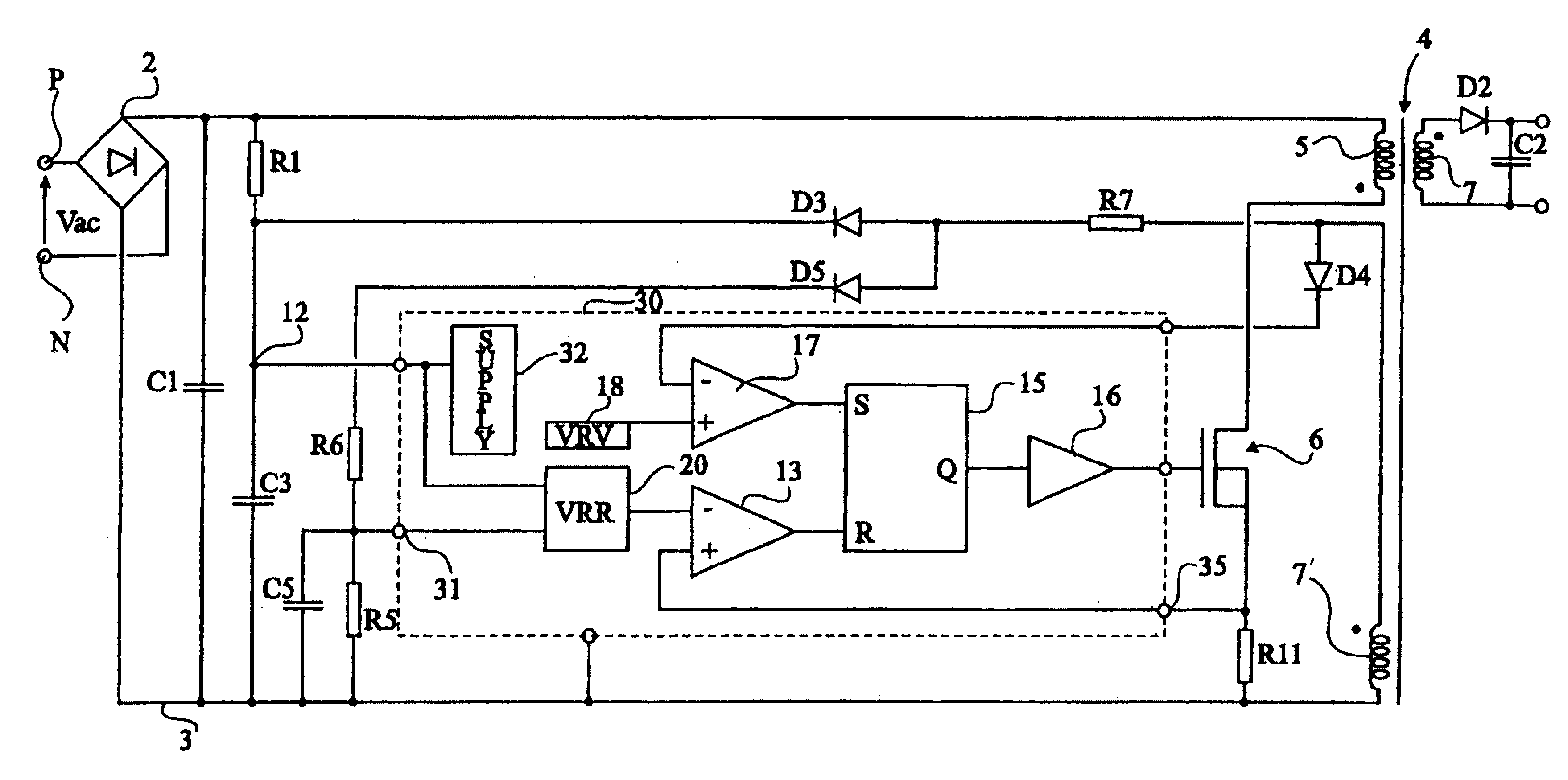
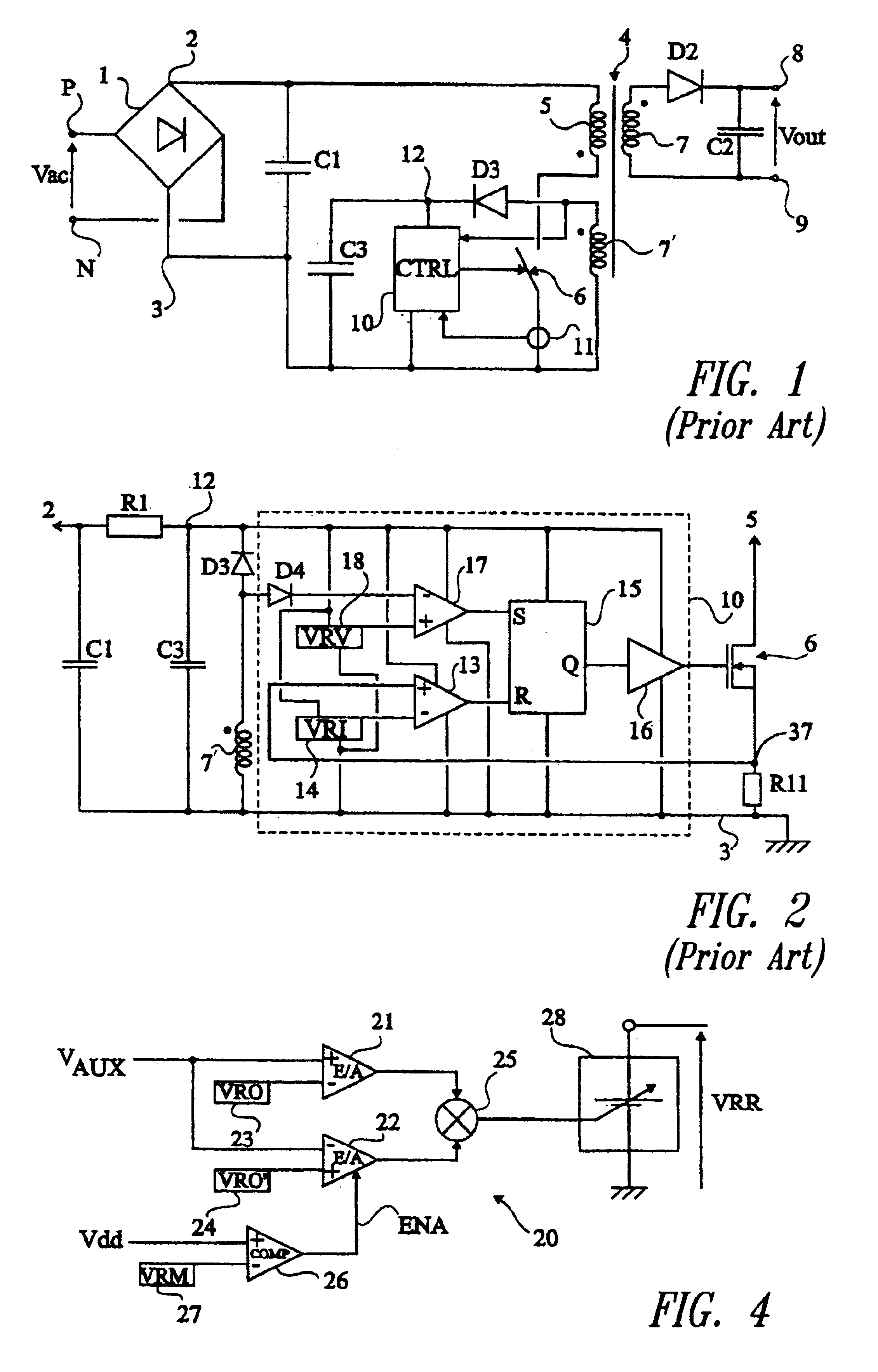
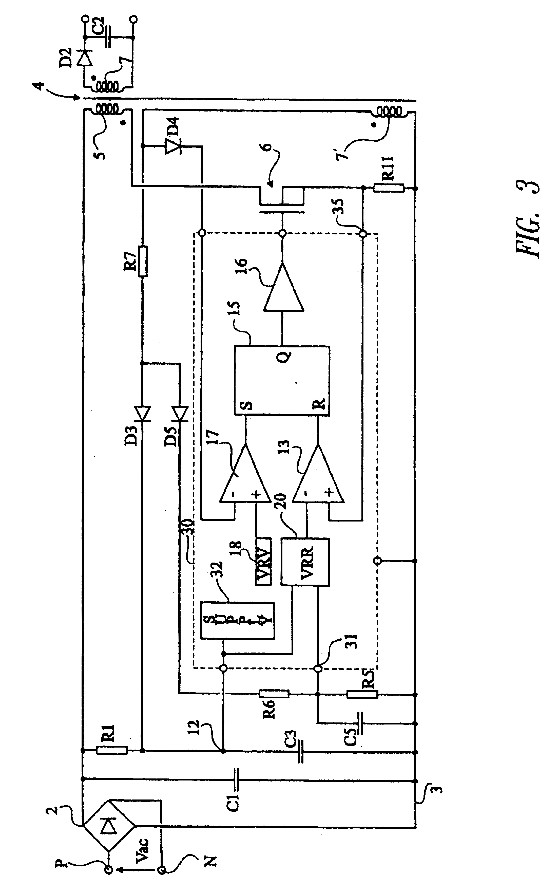
[0034]The same elements have been designated with the same references in the different drawings. The timing diagrams of FIG. 5 are not to scale. For clarity, only those elements of a voltage converter which are useful to the understanding of the present invention have been shown in the drawings and will be described hereafter. In particular, the structures of the fixed reference voltage generation circuits, of the drivers, of the comparators, and of the flip-flop have not been detailed and are no object of the present invention.

[0035]A feature of the present invention is to use an image of the voltage across the secondary winding providing the output voltage to modulate the reference voltage of the comparator conditioning the duration of the on state of the switch. In other words, it is provided to make the reference voltage used to turn the supply voltage switch on variable, and to make this variation a function of the output voltage. A regulation of this output voltage is thus obt...


PUM


Abstract

A voltage converter including a transformer having a primary winding connected in series with a switch for cutting-up a supply voltage and having a secondary winding associated with a capacitor providing a D.C. low voltage, and a self-oscillating control circuit of the switch for detecting the end of the demagnetization of an auxiliary winding of the transformer, to turn the switch on, and for detecting the current in the on-state switch to turn it off when this current reaches a reference point. The reference point is made variable according to the voltage across the auxiliary winding.

Description

BACKGROUND OF THE INVENTION[0001]1. Field of the Invention[0002]The present invention relates to the field of voltage converters of low voltage switched-mode power supply type. The present invention more specifically relates to isolated power supplies, that is, power supplies having no common point between the input voltage (for example, the A.C. supply system) and the regulated D.C. output voltage. The isolation is obtained by means of a transformer having a primary winding associated with a switch and a secondary winding associated with a diode and with a capacitor providing the output voltage. The present invention more specifically relates to so-called self-oscillating converters, in which the switch is controlled in frequency modulation, as opposed to converters having their switch controlled in pulse-width modulation.[0003]2. Description of the Related Art[0004]FIG. 1 shows a conventional example of a switched-mode power supply of the type to which the present invention applie...

Claims


Application Information

Patent Timeline
IPC IPC(8): H02M3/338H02M3/24
CPCH02M3/3385
Inventor BIMBAUD, IGOR
Owner STMICROELECTRONICS SRL
Why Eureka
Try Eureka