Ink-jet recording unit, ink-jet recording method and recording head cleaning method for ink-jet recording unit

a technology of ink-jet recording unit and recording head, which is applied in the direction of printing, etc., can solve the problem of not being able to completely remove the caked-on colorant particles, and achieve the effect of stabilizing the ink travel and preventing the adhesion of colorant particles

Inactive Publication Date: 2005-11-15
FUJIFILM HLDG CORP +1
View PDF3 Cites 7 Cited by
  • Summary
  • Abstract
  • Description
  • Claims
  • Application Information

AI Technical Summary

Benefits of technology

[0012]The invention has been accomplished in view of the aforementioned circumstances and aims at providing an ink-jet recording unit which is capable of stabilizing the travel of ink at the tip of an ink guide and preventing adhesion of colorant particles to the inner wall of the ink guide for smooth ejection of ink as well as removing caked-on colorant particles.

Problems solved by technology

As the colorant particles deposit further, the amount of ink ejected from each ink guide is reduced, thus causing the dot diameter for drawing on a recording medium to be erroneous and preventing ejection of ink, which interferes with drawing.
This cannot completely remove the caked-on colorant particles.

Method used


Image

  • Ink-jet recording unit, ink-jet recording method and recording head cleaning method for ink-jet recording unit
  • Ink-jet recording unit, ink-jet recording method and recording head cleaning method for ink-jet recording unit
  • Ink-jet recording unit, ink-jet recording method and recording head cleaning method for ink-jet recording unit

Examples


embodiment 1

[Embodiment 1]

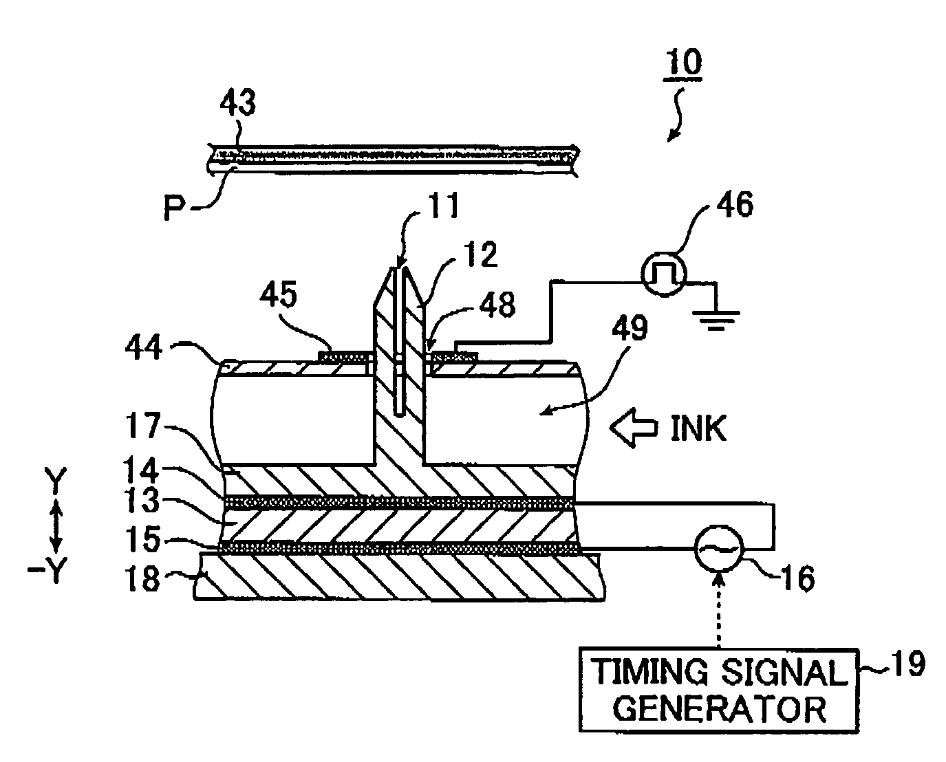
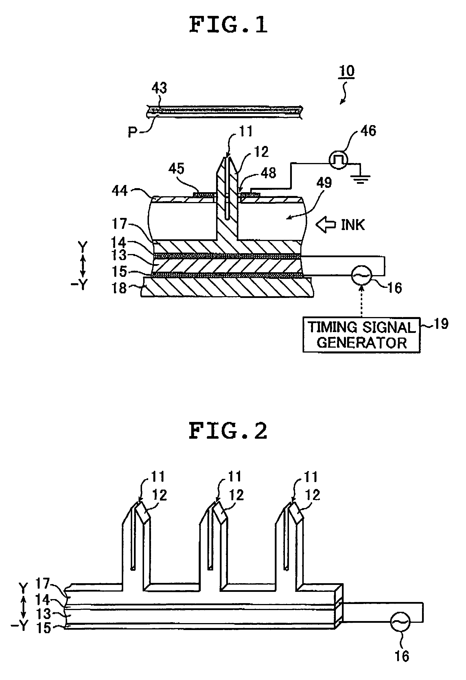
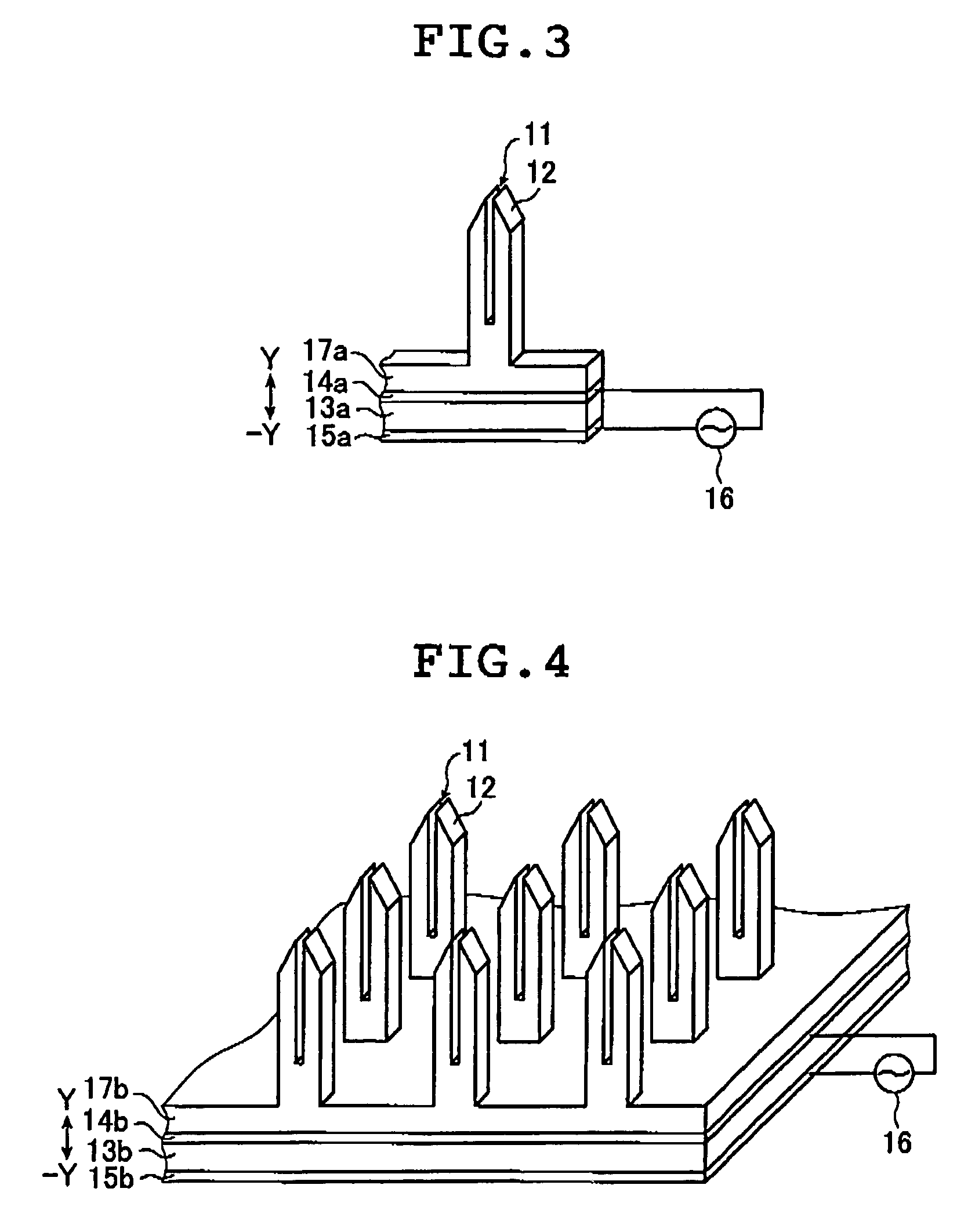
[0055]FIG. 1 is a conceptual illustration explaining an ink-jet recording unit according to Embodiment 1 of the invention. The same components as the prior art components shown in FIGS. 10 and 11 are given the same signs and numerals. An ink-jet recording unit 10 comprises a plurality of ink guides 12 formed in a horizontally linear arrangement as shown, each formed in the shape of an inverted T so as to support by a horizontal face of a bottom section 17 a notch-shaped narrow channel 11 open in a vertical direction in FIG. 1 to guide ink as a dispersion of charged colorant particles in a solvent to a tip open by way of the capillary action so that the narrow channel 11 will extend in the vertical direction in FIG. 1. The ink guides 12 penetrate through holes 48 of an insulated substrate 44. The tip of each ink guide 12 protrudes above the topside of the insulated substrate 44 as shown in FIG. 1. The ink guide 12 may be formed to integrate a convex section provided wit...

embodiment 2

[Embodiment 2]

[0086]Embodiment 2 differs from Embodiment 1 in terms of the vibration mechanism of an ink guide. In Embodiment 1, the vibration of a piezoelectric element is transmitted to the ink guide to shake the ink. In Embodiment 2, the ink guide itself vibrates to shake the ink. This mechanism is detailed below. In the description of Embodiment 2, same signs and numerals are given to the same components as those of the prior art or Embodiment 1. In case description is similar between Embodiment 1 and Embodiment 2, the signs and numerals at a similar section in Embodiment 1 shall be read as those in Embodiment 2. When there is no particular need to do so, description is omitted. The colorant particles in Embodiment 2 are the same as those in Embodiment 1.

[0087]FIG. 5 is a conceptual illustration explaining an ink-jet recording unit according to Embodiment 2 of the invention. The ink-jet recording unit 20 comprises: a plurality of ink guides 22 formed in a horizontally linear arr...

embodiment 3

[Embodiment 3]

[0101]Embodiment 3 differs from Embodiments 1 and 2 in terms of the ink shaking mechanism. In Embodiment 1 above, the vibration of a piezoelectric element is transmitted to the ink guide to shake the ink. In Embodiment 2, the ink guide itself vibrates to shake the ink. That is, in Embodiment 1 or 2, the ink guide vibrates to shake the ink in a narrow channel. Meanwhile, in Embodiment 3, the ink in the channel 49 is shaken and the resulting undulations are transmitted to the ink in the narrow channel. This mechanism is detailed below. In the description of Embodiment 3, same signs and numerals are given to the same components as those of the prior art or Embodiments 1 and 2. In case description is similar between Embodiment 3 and Embodiment 1 or 2, the signs and numerals at a similar section in Embodiment 1 or 2 shall be read as those in Embodiment 3. When there is no particular need to do so, description is omitted. The colorant particles in Embodiment 3 are the same a...


PUM


Abstract

The ink-jet recording unit and method apply a voltage identical in polarity with charged colorant particles agglomerated at a tip of each of ink guides to an ejecting electrode, eject ink from the tip and shake the colorant particles at the tip to agglomerate the colorant particles at the tip in preparation for a subsequent ejection of the ink. The recording head cleaning method for the ink-jet recording unit fills the ink channel with a cleaning solution and shakes the cleaning solution to clean the ink guides.

Description

BACKGROUND OF THE INVENTION[0001]The present invention relates to an ink-jet recording unit, an ink-jet recording method and a recording head cleaning method for the ink-jet recording unit employed by electronic equipment such as a printer, a facsimile, and a copier. The present invention relates in particular to a technology which guides ink to the tip of an ink guide arranged in an ink channel to feed ink in the form of a dispersion of charged colorant particles in a solvent to agglomerate the colorant particles, applies a voltage having the same polarity as that of the colorant particles to an ejecting electrode positioned between the ink level in the ink channel and the tip of the ink guide, thereby ejecting the ink from the tip of the ink guide by way of a repulsion exerted between the ejecting electrode and the colorant particles and ejecting the ink onto a recording medium for recording onto the recording medium, and further in particular to a technology useful in preventing ...

Claims


Application Information

Patent Timeline
Patent Type & Authority Patents(United States)
IPC IPC(8): B41J2/06B41J2/04B41J2/175B41J2/165
CPCB41J2/06
Inventor KAGAMI, TAMITO
Owner FUJIFILM HLDG CORP
Why Eureka
Try Eureka