Atmospheric and/or differential pressure closure for an evacuable storage container

a technology for evacuable storage containers and differential pressure, which is applied in the direction of flexible container closures, ventilation means, transportation and packaging, etc., can solve the problems that the use of this type of seals may not adequately prevent the leakage of gases back into the bag, and achieve the effect of preventing the separation of the profiles and the leakage of fluids therebetween

Inactive Publication Date: 2005-11-15
ERKENBRACK KENNETH BERESFORD
View PDF11 Cites 42 Cited by
  • Summary
  • Abstract
  • Description
  • Claims
  • Application Information

AI Technical Summary

Benefits of technology

[0010]The sealing technology offered herein is unique as well as robust, being analogous to the well known practice of placing a suction cup on a flat smooth surface, pressing it down to expel the air from under the cup, thus producing a vacuum thereunder, whereupon atmospheric pressure at 14.7 pounds per square inch (psi) now presses against this vacuum, holding the cup tightly to said surface. If all the air were expelled from under the cup, the pressure holding the cup to the surface would be equal to the ambient atmospheric pressure, normally at 14.7 pounds per square inch at seal levels which, while unlikely or unnecessary to achieve, does teach the degree of the force which may be captured or harnessed to aid the sealing integrity of the invention specified herein.
[0027]It is an additional object of the invention to provide a pair of flexible mating strips that comprise profiles having a shape and pliability such that when closed and experiencing any differential pressures, the sealing integrity increases without flattening the surfaces exposed to the pressures and preventing separation of the profiles and leaking of fluids therebetween.

Problems solved by technology

The use of this type of seal may not adequately prevent leakage of gases back into the bag after a vacuum source is connected to the bag.

Method used


Image

  • Atmospheric and/or differential pressure closure for an evacuable storage container
  • Atmospheric and/or differential pressure closure for an evacuable storage container
  • Atmospheric and/or differential pressure closure for an evacuable storage container

Examples


third embodiment

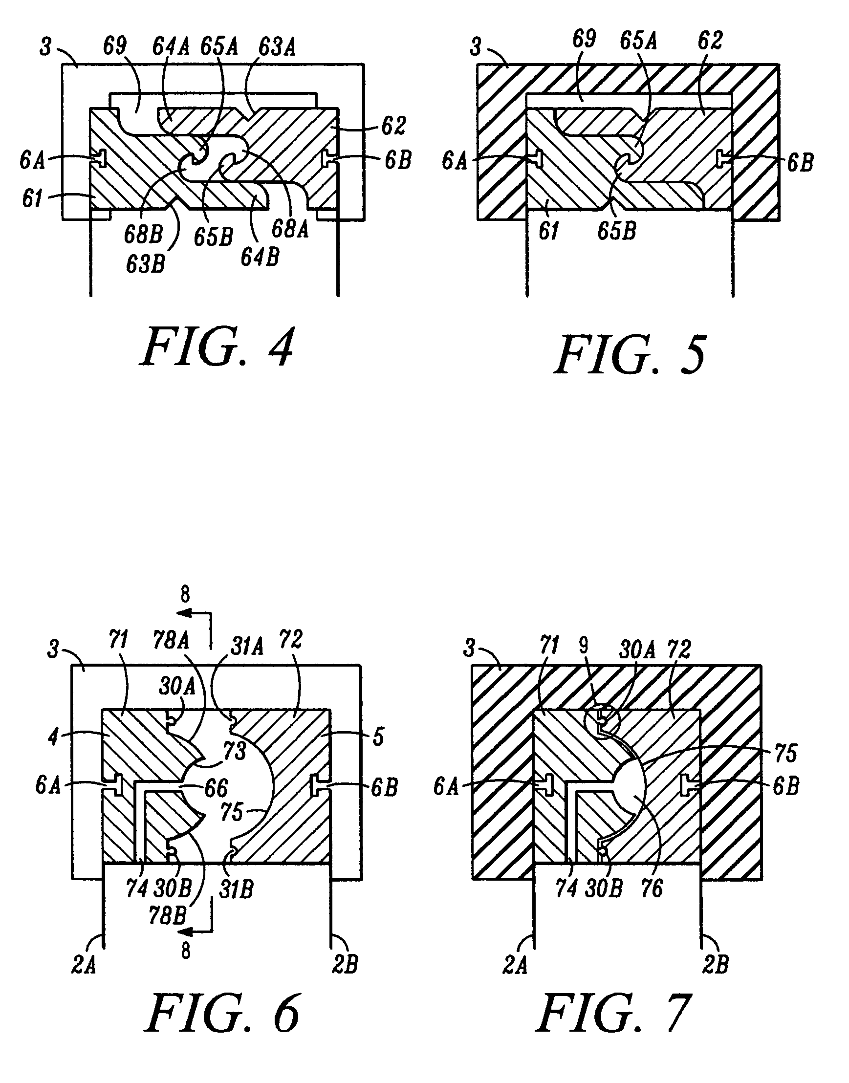
[0053]FIGS. 6 through 9 show the invention. Track 71 includes an upper and lower longitudinal ridge 30A and 30B for mating with complementary upper and lower longitudinal grooves 31A and 31B of track 72, as clearly shown in FIG. 9. In this embodiment, track 71 includes a vacuum channel 74 and 66 for applying a negative pressure therein to ensure that tracks 71 and 72 are securely seated when the vacuum source is connected to bag 1. An arcuate opening 73 is provided at the opening 66 of the vacuum channel 74. Upper and lower sealing surfaces 78A and 78B are arranged near and on opposite sides of arcuate opening 73.

[0054]FIG. 7 shows the embodiment of FIG. 6 in a closed position. When a vacuum is introduced into bag 1, a negative pressure is exerted through vacuum channel 74 into arcuate vacuum chamber 76 causing arcuate sidewall 75 to be pulled towards and seat against upper and lower sealing surfaces 78A and 78B to assure a tight seal as shown. Vacuum openings 66 may be strategicall...

fourth embodiment

[0055]FIGS. 10 through 12 show the sealing means for the present invention. Track 80 includes a hook-shaped longitudinal ridge 91A positioned above a curvilinear groove 93A. A hook-shaped longitudinal ridge 91B is arranged near a bottom of the track 80 below a second curvilinear groove 93B. Curvilinear grooves 93A and 93B define and end at surface area 95 of vacuum channel 74.

[0056]Track 81 comprises complementary grooves 92A and 92B arranged on an upper and lower surface of the track 81 as shown. These grooves 92A and 92B accept and lock with hook-shaped longitudinal ridges 91A and 91B thus allowing 94A and 94B to mate and melt with 93A and 93B following the initiation of a vacuum within FIG. 1. The point of contact between the ridges and grooves are arcuate to provide a larger contact area.

[0057]Each track 80 and 81 includes collapsible flex openings 85 near the top and bottom exterior surfaces for allowing the tracks to deform when a vacuum connected to the bag 1. When sealed, as...


PUM


Abstract

An evacuable bag or container for items which benefit from being stored in a vacuum environment by reason that the bag or container is impermeable to air or liquid, with a first opening for entrance or closure purposes, which first opening has a zipper sealing closure adjacent thereto and integral with said bag or container for closing and opening purposes, the sealing integrity of which is aided by atmospheric and / or differential pressures, and a second opening, with an exit-only valve therein, for connection purposes to an external vacuum source, by which means said bag or container can be evacuated of air or liquid. Thus, this invention provides the constituent key to a relatively inexpensive appliance system for home vacuum packaging of perishables and / or items requiring compression packaging due to limited storage space.

Description

[0001]The present invention claims priority from U.S. Provisional Patent Applications Ser. No. 60 / 490,985 filed Jul. 30, 2003, Ser. No. 60 / 494,853 filed Aug. 14, 2003 and Ser. No. 60 / 527,536 filed Dec. 8, 2003. The patent application includes materials submitted in Disclosure Documents Ser. No. 537319 filed Aug. 28, 2003, Ser. No. 538299 filed Sep. 12, 2003, Ser. No. 542617 filed Nov. 24, 2003, and Ser. No. 543825 filed Dec. 19, 2003.[0002]The present application received no federal research and development funding.FIELD OF THE INVENTION[0003]Generally, the present invention relates to closures for storage containers such as plastic bags. More specifically, the invention relates to a flexible storage container and associated system for use in storing articles or goods in a vacuum sealed environment. The storage container may comprise nylon or other impermeable material.[0004]The word “fluid” is referenced throughout the application and should be interpreted broadly to include both l...

Claims


Application Information

Patent Timeline
Patent Type & Authority Patents(United States)
IPC IPC(8): B65D33/25B65D77/22B65D81/20
CPCB65D33/2591B65D77/225B65D81/2023Y10T24/45157B65D2205/00B65D33/2508
Inventor ERKENBRACK, KENNETH BERESFORD
Owner ERKENBRACK KENNETH BERESFORD
Why Eureka
Try Eureka