Annulotomy closure device

a technology of annuloplasty and closure device, which is applied in the field of annuloplasty closure device, can solve the problems of herniated disc, hole may become enlarged or elongated in nature, and is vulnerable to pressure, and achieves the effect of enhancing tissue growth and encouraging rapid healing

Inactive Publication Date: 2005-11-15
NUVASIVE
View PDF31 Cites 256 Cited by
  • Summary
  • Abstract
  • Description
  • Claims
  • Application Information

AI Technical Summary

Benefits of technology

[0005]The present invention provides methods and apparatus for the closure of holes, including surgical access holes formed in a rigid or semi-rigid body, and is particularly useful in closing a surgical access hole in an intervertebral disc. As such, the present invention provides systems of annulotomy closure which reduce the risks of reherniation.
[0016]Advantages of both aspects of the present invention include its encouragement of rapid healing by providing a lattice structure to enhance tissue growth. Moreover, the present annulotomy closure systems are also able to accommodate the various sizes and geometries of annular holes that may be encountered by the surgeon. Furthermore, the present annulotomy closure systems all provide compensation for normal movement during patient healing since the system itself remains transversely flexible but is positionally stable along its longitudinal axis. A further advantage of the present system is that should any portion of the mesh remain on the outside of the hole on the annulus, this would be atraumatic to adjacent nerves in close proximity to the device due to the soft and flexible nature of the mesh material.

Problems solved by technology

Due to the location of the nerve roots, they are vulnerable to pressure from a herniated disc.
Furthermore, as instruments are passed through the circular hole, the hole may become enlarged or elongated in nature upon completion of the procedure.
Due to the semi-rigid nature of the annular tissue, closure by means of traditional tissue approximation techniques, such as suturing, is nearly impossible.
Closure is further complicated by the proximity of nerves and the depth of the access hole below the surface of the skin.
As a complication of disc excision surgery, such annular defects can represent a potential liability with respect to subsequent recurrent disc herniations.
These high pressures can cause the nucleus pulposus to be extruded through the open hole and impinge upon nearby nerves, thus causing a reoccurrence of the original symptoms that the surgeon intended to treat.

Method used


Image

  • Annulotomy closure device
  • Annulotomy closure device
  • Annulotomy closure device

Examples


Embodiment Construction

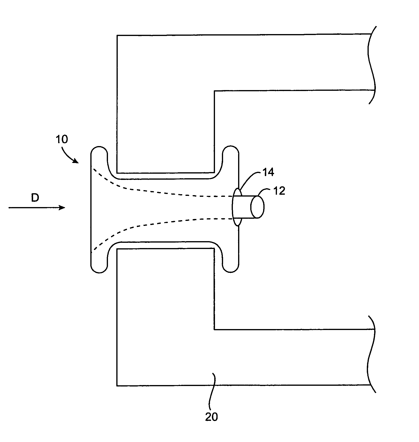
[0039]The present invention provides methods and apparatus for sealing holes in various bony structures. In a preferred aspect, the present invention provides methods and apparatus for sealing a surgical hole drilled in a patient's annulus. As such, the present invention is ideally suited to seal a hole drilled in an intervertebral disc such that nucleus pulposus on the inside of the disc cannot seep or flow through the hole to the outside of the disc as the disc is compressed during normal movement. The present system is not limited only to sealing holes which have been drilled in an annulus, but may also be used to seal naturally occurring holes as well. Moreover, the present invention is not limited to sealing holes in the annulus alone but may be used to seal any hole, thereby inhibiting the passage of soft tissue therethrough.

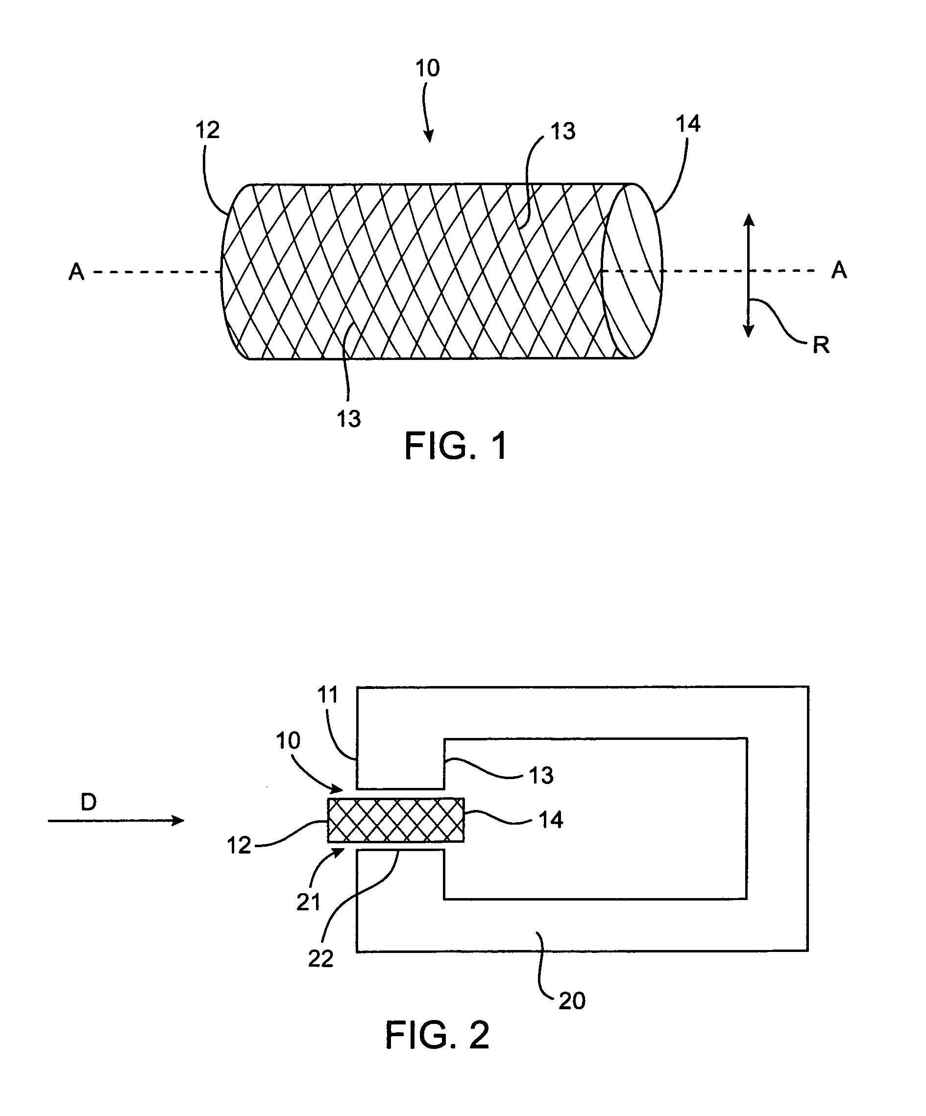
[0040]FIG. 1 shows a generally cylindrical tubular mesh which is comprised of a, multiplicity of monofillament or multifilliar strands 13 of suture-type m...


PUM


Abstract

A system for sealing a hole in a body, comprising a generally cylindrical mesh formed from a plurality of helical strands which is inserted into the hole, with at least one end of the cylindrical mesh being moved least partially through an interior portion of the cylindrical shaped mesh such that the mesh expands radially outwards against sides of the hole.

Description

CROSS-REFERENCES TO RELATED APPLICATIONS[0001]The present application is a continuation application claiming priority from Provisional U.S. Patent Application No. 60 / 154,969 filed Sep. 20, 1999, which is incorporated herein by reference in its entirety for all purposes.TECHNICAL FIELD[0002]The present invention relates to systems for sealing holes in body parts and to sealing surgically formed holes in a bony structure in general and in particular to systems for providing closure of a surgical access hole in an intervertebral disc following an annulotomy.BACKGROUND OF THE INVENTION[0003]Each intervertebral disc has a firm outer layer, called the annulus fibrosus, and a gelatinous interior called the nucleus pulposus. The annulus fibrosus acts as a semi-rigid elastic pressure vessel to contain the nucleus pulposus, therefore creating a compliant interface between the relatively rigid vertebrae above and below each disc. Adjacent to each disc, a pair of nerve roots pass from the spina...

Claims


Application Information

Patent Timeline
Patent Type & Authority Patents(United States)
IPC IPC(8): A61B17/68A61B17/00A61F2/00A61F2/44A61M29/00
CPCA61B17/0057A61B17/68A61F2/442A61B2017/00261A61B2017/00575A61B2017/00592A61B2017/00601A61B2017/00606A61B2017/00619A61B2017/00623A61B2017/00654A61F2/0063A61F2002/0072A61F2002/3008A61F2002/30171A61F2002/30224A61F2002/30461A61F2002/30571A61F2002/30579A61F2002/4435A61F2002/4495A61F2220/0075A61F2230/005A61F2230/0069A61F2250/0098A61M29/02A61F2002/0068
Inventor MATSUURA, DAVID G.GILLESPIE, WALTER D.MARINO, JAMES F.PASTORE, SELISE M.
Owner NUVASIVE
Why Eureka
Try Eureka